Content .. 2216 2217 2218 2219 ..
Nissan Qashqai J11. Manual - part 2218
DAS-286
< DTC/CIRCUIT DIAGNOSIS >
[CHASSIS CONTROL]
U1000-00 CAN COMM CIRCUIT
U1000-00 CAN COMM CIRCUIT
DTC Logic
INFOID:0000000010417041
DTC DETECTION LOGIC
Diagnosis Procedure
INFOID:0000000010417042
1.
PERFORM SELF DIAGNOSTIC RESULT
1.
Turn ignition switch ON and wait for 2 seconds or more.
2.
Perform Self Diagnostic Result for CHASSIS CONTROL.
Is DTC “U1000-00” detected?
YES
>> Refer to
LAN-24, "Trouble Diagnosis Flow Chart"
NO
>> Refer to
GI-41, "Intermittent Incident"
.
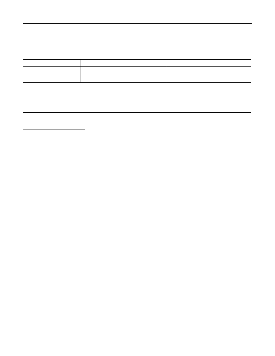
CONSULT Display
DTC Detection Condition
Possible Cause
CAN COMM CIRCUIT
[U1000-00]
Chassis control module is not transmitting or re-
ceiving CAN communication signal for 2 seconds
or more.
CAN communication system.