Content .. 2094 2095 2096 2097 ..
Nissan Qashqai J11. Manual - part 2096
AV
DIAGNOSIS SYSTEM (AUDIO UNIT)
AV-73
< SYSTEM DESCRIPTION >
[DISPLAY AUDIO]
C
D
E
F
G
H
I
J
K
L
M
B
A
O
P
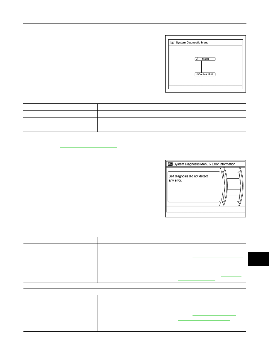
2.
Self diagnosis screen is displayed. The bar graph visible in center of screen indicates progress of self
diagnosis.
3.
Diagnosis results are displayed after the self diagnosis is com-
pleted. The unit names and the connection lines are color coded
according to the diagnostic results.
1: Control unit (audio unit) is displayed in red.
• Replace audio unit if Self Diagnosis did not run because control unit malfunction is indicated. The symptom is audio unit internal
error. Refer to
AV-114, "Removal and Installation"
.
• If multiple errors occur at the same time for a single unit, the screen switch colors are determined according to the following order
of priority: red > gray.
4.
Comments of self diagnosis results can be viewed in the diagno-
sis result screen.
Audio Unit Self Diagnosis Results
AWNIA2630GB
Diagnosis results
Unit
Connection line
Normal
Green
Green
Connection malfunction
Gray
Yellow
Unit malfunction
1
Red
Green
JSNIA1870ZZ
Only Unit Part Is Displayed In Red
Screen switch
Description
Possible cause
Control unit
Malfunction is detected in audio unit power
supply and ground circuits.
• Audio unit power supply or ground cir-
cuits.
Refer to
• If no malfunction is detected in audio unit
power supply and ground circuits, re-
place audio unit. Refer to
.
A Connecting Cable Between Units Is Displayed In Yellow
Area with yellow connection lines
Description
Possible cause
Control unit
⇔
Meter
When one of the following is detected:
• malfunction is detected in combination
meter power supply and ground circuits.
• malfunction is detected in AV communi-
cation circuits between audio unit and
combination meter.
• Combination meter power supply or
ground circuits.
Refer to
.
• AV communication circuits between au-
dio unit and combination meter.