Content .. 1848 1849 1850 1851 ..
Nissan Qashqai J11. Manual - part 1850
BCS-126
< DTC/CIRCUIT DIAGNOSIS >
COMBINATION SWITCH OUTPUT CIRCUIT
COMBINATION SWITCH OUTPUT CIRCUIT
Diagnosis Procedure
INFOID:0000000010378039
1.
CHECK OUTPUT 1 - 5 CIRCUIT FOR OPEN
1.
Turn ignition switch OFF.
2.
Disconnect BCM and combination switch connectors.
3.
Check continuity between BCM harness connector and combination switch harness connector.
Does continuity exist?
YES
>> GO TO 2.
NO
>> Repair harnesses or connectors.
2.
CHECK OUTPUT 1 - 5 CIRCUIT FOR SHORT
Check for continuity between BCM harness connector and ground.
Does continuity exist?
YES
>> Repair harnesses or connectors.
NO
>> GO TO 3.
3.
CHECK COMBINATION SWITCH INTERNAL CIRCUIT
1.
Connect BCM connector.
2.
Turn ON any switch in the system that is malfunctioning.
3.
Check voltage between BCM harness connector and ground.
NOTE:
Check that the combination switch outputs a signal from combination switch input system.
Is the measurement value normal?
YES
>> Replace BCM. Refer to
BCS-132, "Removal and Installation"
.
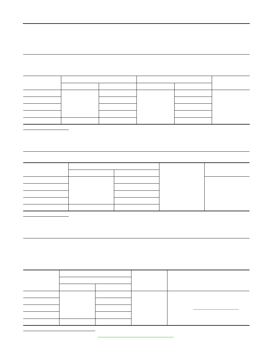
System
BCM
Combination switch
Continuity
Connector
Terminal
Connector
Terminal
OUTPUT 1
M69
85
M20
7
Existed
OUTPUT 2
84
15
OUTPUT 3
86
10
OUTPUT 4
87
5
OUTPUT 5
M70
74
2
System
BCM
Ground
Continuity
Connector
Terminal
OUTPUT 1
M69
85
Not existed
OUTPUT 2
84
OUTPUT 3
86
OUTPUT 4
87
OUTPUT 5
M70
74
System
(+)
(
−
)
Voltage
(Approx.)
BCM
Connector
Terminal
OUTPUT 1
M69
85
Ground
Refer to
OUTPUT 2
84
OUTPUT 3
86
OUTPUT 4
87
OUTPUT 5
M70
74