Content .. 1849 1850 1851 1852 ..
Nissan Qashqai J11. Manual - part 1851
BCS-130
< SYMPTOM DIAGNOSIS >
COMBINATION SWITCH SYSTEM SYMPTOMS
SYMPTOM DIAGNOSIS
COMBINATION SWITCH SYSTEM SYMPTOMS
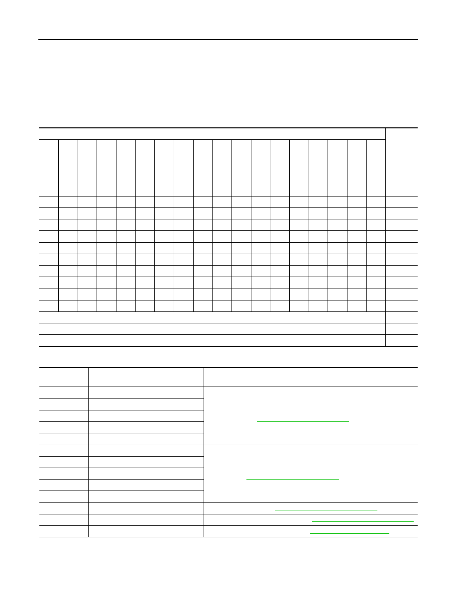
Symptom Table
INFOID:0000000010378041
1.
Perform “Data Monitor” of CONSULT to check for any malfunctioning item.
2.
Check the malfunction combinations.
Malfunction item:
×
3.
Identify the malfunctioning part from the agreed combination and repair or replace the part.
Data monitor item
Malfunc-
tion com-
bination
FR WIPE
R HI
F
R
WIPER LOW
FR W
ASHER S
W
FR
W
IP
E
R
I
N
T
WIP VOLUME
RR WIPER ON
R
R
WIPER
IN
T
RR W
ASHER SW
TURN SIGNAL R
T
U
R
N
SIGNAL L
T
A
IL LAM
P
SW
HI BEAM
SW
HE
A
D
LA
MP
S
W
LIGHT OFF
SW
P
ASSING SW
AUT
O
LI
GHT
SW
FR FOG SW
RR FOG SW
×
×
×
A
×
×
×
×
B
×
×
×
×
C
×
×
×
×
D
×
×
×
×
E
×
×
×
×
F
×
×
×
×
G
×
×
×
×
H
×
×
×
×
I
×
×
×
J
All Items
K
If only one item is detected or the item is not applicable to the combinations A to K
L
All Items are normal
M
Malfunction
combination
Malfunctioning part
Repair or replace
A
Combination switch OUTPUT 1 circuit
Inspect the combination switch output circuit applicable to the malfunction-
ing part. Refer to
BCS-128, "Diagnosis Procedure"
.
B
Combination switch OUTPUT 2 circuit
C
Combination switch OUTPUT 3 circuit
D
Combination switch OUTPUT 4 circuit
E
Combination switch OUTPUT 5 circuit
F
Combination switch INPUT 1 circuit
Inspect the combination switch input circuit applicable to the malfunctioning
part. Refer to
BCS-126, "Diagnosis Procedure"
G
Combination switch INPUT 2 circuit
H
Combination switch INPUT 3 circuit
I
Combination switch INPUT 4 circuit
J
Combination switch INPUT 5 circuit
K
BCM
Replace BCM. Refer to
BCS-132, "Removal and Installation"
.
L
Combination switch
Replace combination switch. Refer to
BCS-133, "Removal and Installation"
M
Connector and harness
Check intermittent incident. Refer to
GI-41, "Intermittent Incident"
.