Content .. 1303 1304 1305 1306 ..
Nissan Qashqai J11. Manual - part 1305
BACK DOOR
DLK-489
< REMOVAL AND INSTALLATION >
[TYPE 3]
C
D
E
F
G
H
I
J
L
M
A
B
DLK
N
O
P
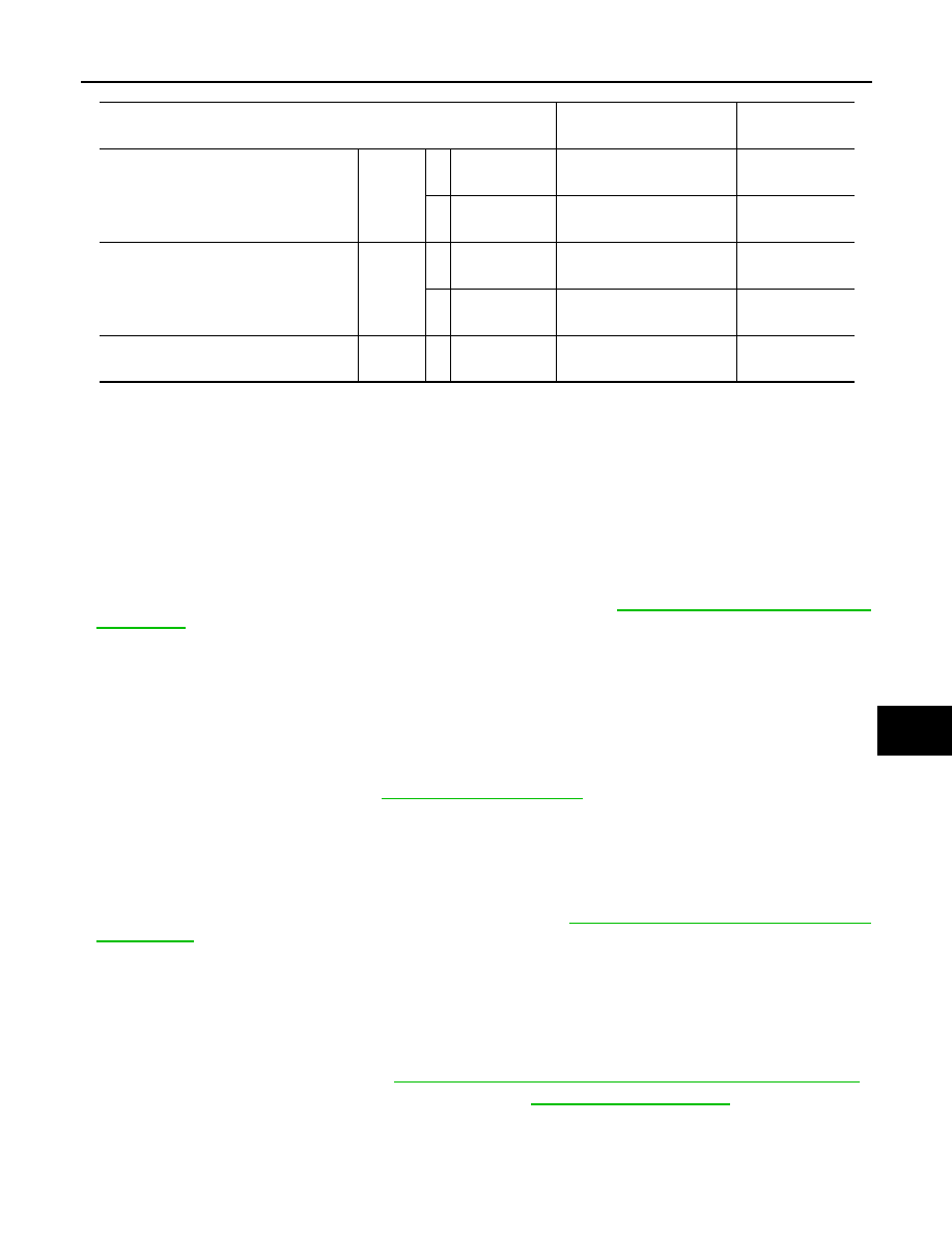
Unit: mm [in]
Fitting Adjustment Procedure
1.
Loosen back door striker mounting TORX bolts.
2.
Loosen back door hinge mounting nuts (back door side).
3.
Adjust back door using back door striker, back door hinge and back door bumper rubber to the specified
value, as shown in the following table.
4.
After adjustment tighten back door striker mounting bolts and back door hinge mounting nuts (back door
side) to the specified torque.
CAUTION:
• Apply touch-up paint to the body color if the paint around back door hinge, and back door hinge
mounting nuts is peeled off.
• Check back door hinge rotating part for poor lubrication. Refer to
BACK DOOR STRIKER ADJUSTMENT
Adjust back door striker so that it becomes parallel with back door lock insertion direction.
BACK DOOR STRIKER
BACK DOOR STRIKER : Removal and Installation
INFOID:0000000010479373
REMOVAL
1.
Remove luggage rear plate. Refer to
2.
Remove TORX bolts, and then remove back door striker.
INSTALLATION
Note the following items, and install in the reverse order of removal.
CAUTION:
• Never reuse mounting TORX bolt. Always replace it with a new one when it is removed.
• After installation, perform the fitting adjustment. Refer to
DLK-487, "BACK DOOR ASSEMBLY :
• After installation, check back door open/close, lock/unlock operation.
BACK DOOR HINGE
BACK DOOR HINGE : Removal and Installation
INFOID:0000000010479374
REMOVAL
1.
Remove back door assembly. Refer to
DLK-486, "BACK DOOR ASSEMBLY : Removal and Installation"
2.
Remove luggage side upper finisher LH and RH. Refer to
3.
Lower the rear end of headlining to secure work space.
4.
Remove back door hinge mounting nut, and then remove back door hinge.
INSTALLATION
Portion
Standard
Difference
(RH/LH,MAX)
Back door – Roof panel
A – A
D
Clearance
5.0 – 7.0
[0.197 – 0.276]
—
E
Surface
height
0 – 2.0
[0 – 0.079]
—
Back door – Body side outer
B – B
F
Clearance
2.8 – 7.2
[0.110 – 0.283]
< 2.9
[0.114]
G
Surface
height
0 – 4.0
[0 – 0.157]
< 2.5
[0.098]
Back door – Rear bumper fascia
C – C
H
Clearance
4.8 – 9.2
[0.189 – 0.362]
—