Nissan Qashqai J11. Manual - part 129


  Index      Nissan     Nissan Qashqai J11 - Service and Repair Manual


Search            


Content   ..  127  128  129  130   ..


Nissan Qashqai J11. Manual - part 129


CYLINDER BLOCK

EM-455

< UNIT DISASSEMBLY AND ASSEMBLY >

[R9M]

C

D

E

F

G

H

I

J

K

L

M

A

EM

N

P

O

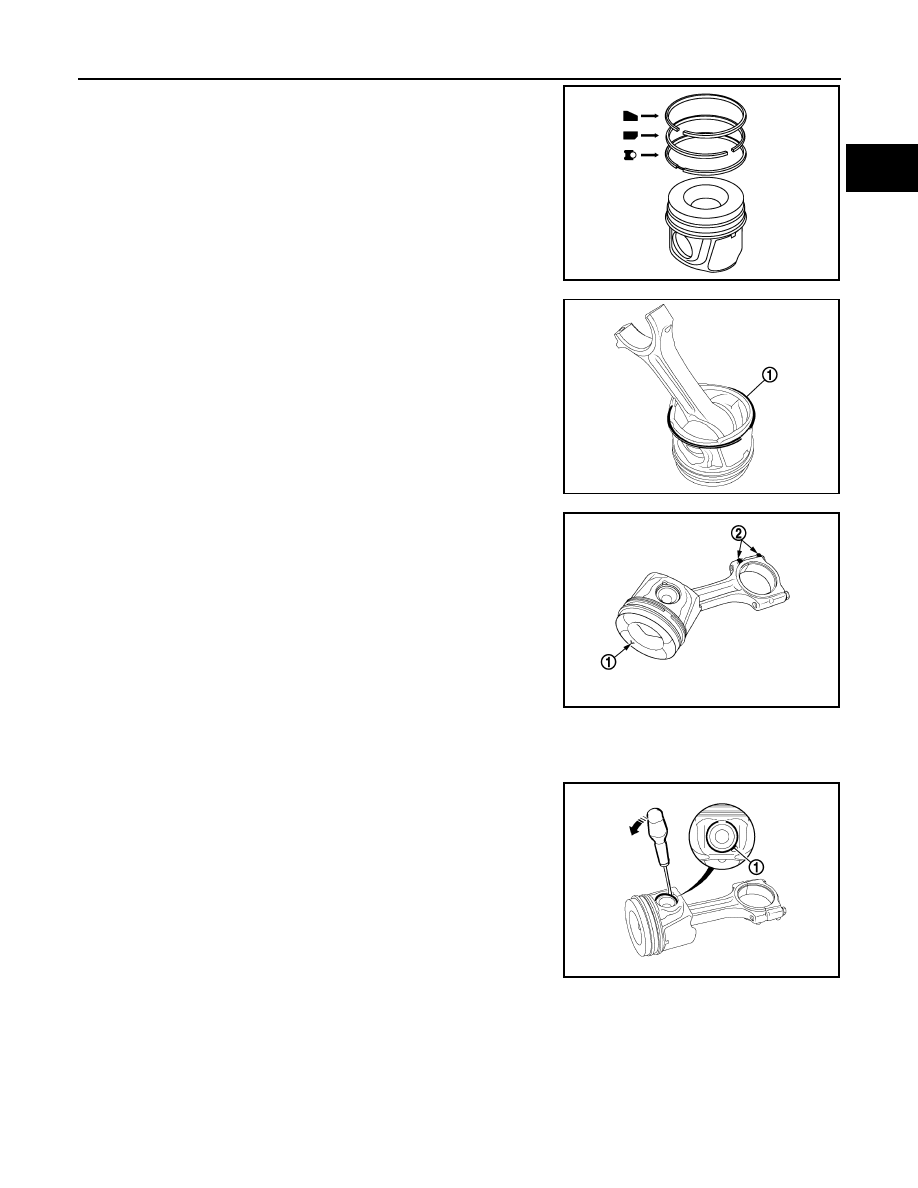
• Position each ring with the gap as shown in the figure referring

to the piston front mark.

8.

• Fit the scraper ring (1) with the hand by way of the con rod. 

9.

• Lubricate piston pin with engine oil.
• Position the con rod in relation to the piston (piston marking (1)

"V" is opposite the machined bosses (2) on the big end)

NOTE:
Piston marking V engine flywheel end, Con rod marking
(machined bosses) timing end. 

10. Engage the pin in the piston and in the samll end.

NOTE:
Check that the piston pin slides and rotates easily in the piston and the small end.

11.

• Refit the locking spring ring to the piston pin using a flat screw-

driver (apply pressure in the groove (1)).

NOTE:
Position the opening in the locking spring ring towards the piston
crown.

JPBIA1058ZZ

E1BIA0503ZZ

E1BIA0504ZZ

E1BIA0505ZZ

EM-456

< UNIT DISASSEMBLY AND ASSEMBLY >

[R9M]

CYLINDER BLOCK

12.

Place: 

• the con rod body on the bench,
• the con rod upper bearing shell (width = [18.2 mm (0.7 in)]

• Secure the flush bearing shell of the con rod body mating face

on side (1) and push from the opposite side until the con rod
body mating face is flush.

Place: 

• the con rod cap on the bench,
• the con rod lower bearing shell (width = [18.2 mm (0.7 in)]

• Secure the flush bearing shell of the con rod cap mating face on side (2) and push from the opposite

side until the con rod cap mating face is flush.

13.

• Mesure the distance (X) between the edge of the bearing shell

and the wall of the con rod body at points (A), (B) and (C).

14.

• Centre the bearing shell on the con rod body.
• Adjust the position of the bearing shell at points (A), (B) and

(C) using a set of feeler gauges = X: [2 mm (0.1 in)].

• Repeat the previous operations on the remaining con rod bod-

ies and caps

Lubricate with engine oils:

• the cylinder block barrels,
• the piston rings
• the piston skirts,
• the crankshaft crankpins

• Orient the piston rings on the piston pin axis.

15. Lubricate the tool [SST: Mot.1979].

E1BIA0506ZZ

E1BIA0507GB

E1BIA0508ZZ

CYLINDER BLOCK

EM-457

< UNIT DISASSEMBLY AND ASSEMBLY >

[R9M]

C

D

E

F

G

H

I

J

K

L

M

A

EM

N

P

O

16.

• Check that the piston rings are correctly engaged in the piston

grooves

• Put the piston on a plane and clean surface.
• Verify the absence of over lap (1) of the tips of the scraper

ring.

NOTE:
Manipulate the piston exclusively by the skirt or the con rod,
without touching the scraper ring.

17.

• Insert the tool [SST: Mot.1979]  (1) on the piston, conical part

the first one, by the con rod.

NOTE:
The engagement of the tool [SST: Mot.1979] on the piston has
to be made without forcing. If resistance during the engagement
occures, put off the tool and to re-engage it.

18.

• Check that the pistons correspond to the cylinder block barrels

(No. 1 timing end)

• Place the "con rod - piston - tool" (1) assembly in the cylinder.
NOTE:
Position the point of the "V" engaged on the piston towards the
flywheel end.

19.

WARNING:

Failure to observe the following procedure may result in destruction of the engine.
• Gradually insert the "con rod - piston" assembly in the cylinder ( avoid any contact between the con rod

and the piston base cooling jet) using only of the hand.

• Position the big end on the crankshaft crankpin.
• Refit the con rod cap, ensuring that the con rod caps and bodies correspond. Refer to 

EM-459, "Inspec-

tion"

.

20.

a.

Tighten new connecting rod cap bolts.

E1BIA0509ZZ

E1BIA0510ZZ

E1BIA0511ZZ

: 25.0 N·m (2.6 kg-m, 18 ft-lb)

EM-458

< UNIT DISASSEMBLY AND ASSEMBLY >

[R9M]

CYLINDER BLOCK

b.

Turn bolts 110 degrees clockwise (angle tightening).

CAUTION:

Confirm the tightening angle by using an angle wrench
[SST: KV10112100 ( — )] (A) or protractor. Never judge by
visual inspection without the tool. 

• After tightening connecting rod cap bolt, check that crankshaft rotates smoothly. 
• Check the connecting rod side clearance. Refer to 

EM-459, "Inspection"

.

• Check the piston protrusion. Refer to 

EM-459, "Inspection"

.

21. Install oil pump and related parts.

22. Install oil pan (upper). Refer to 

EM-437, "Exploded View"

.

23. Install rear oil seal retainer with the following procedure:

a.

Set guide bolt (A) and protector (B) to rear oil seal retainer (1).
NOTE:
The protector is supplied in the new oil seal parts kit.

b.

Move the rear oil seal retainer evenly by hand until it makes con-
tact with the cylinder block.

c.

Tighten mounting bolts in two steps separately in numerical
order as shown in the figure.

i.

Tighten mounting bolts No.1 and 5.

ii.

Tighten mounting bolts No. 1 to 8 in numerical order as shown.

24. Install pilot bushing.

• Using the drift, force fit the pilot bushing until its front end contacts crankshaft.

25. Install flywheel by aligning the mark (1).

NOTE:
The openings of the flywheel bolts must be aligned.

a.

Install bolts without tightening them.

b.

Fix flywheel using flywheel locking tool [SST:  —  (Mot.1431)]. 

JPBIA0846ZZ

JPBIA0777ZZ

: 5.0 N·m (0.51 kg-m, 44 in-lb)

: 12.0 N·m (1.2 kg-m, 106 in-lb)

JPBIA0645ZZ

E1BIA0773ZZ


Content   ..  127  128  129  130   ..