Nissan Qashqai J11. Manual - part 128
CYLINDER BLOCK
EM-451
< UNIT DISASSEMBLY AND ASSEMBLY >
[R9M]
C
D
E
F
G
H
I
J
K
L
M
A
EM
N
P
O
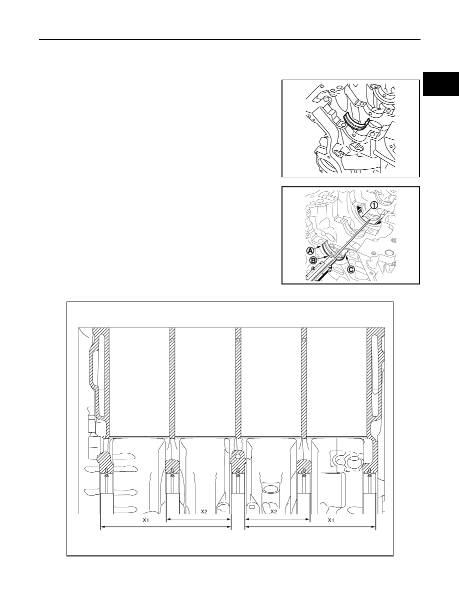
a.
Remove dust, dirt, and engine oil from the bearing mating surfaces of the cylinder block and main bearing
cap.
b.
Centre the grooved bearing shell on bearing No.1 of the cylinder block while aligning the groove of the
bearing shell with the hole of the bearing.
• Secure the flush bearing shell and push from the opposite side
the position of the bearing shell flush with the bearing.
c.
d.
E1BIA0532ZZ
E1BIA0533ZZ
E1BIA0534GB