Nissan Qashqai J11. Manual - part 120
TIMING SPROCKET
EM-419
< REMOVAL AND INSTALLATION >
[R9M]
C
D
E
F
G
H
I
J
K
L
M
A
EM
N
P
O
TIMING SPROCKET
Removal and installation
INFOID:0000000010282007
REMOVAL
1.
Remove the timing chain. Refer to
.
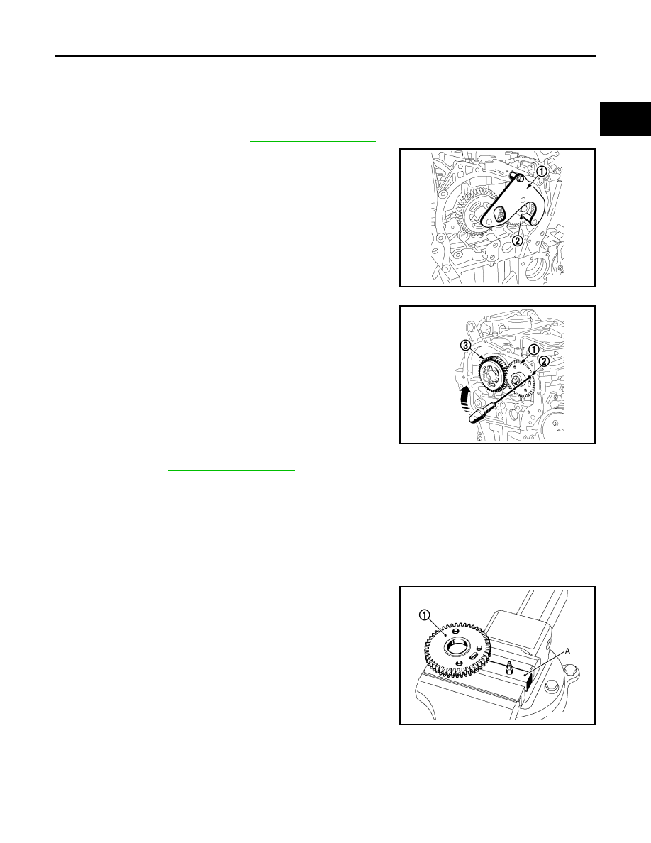
2.
Immobilise the intake camshaft timing sprocket using the tool
[SST: -(Mot.1969)] (1)
3.
Loosen the intake camshaft timing sprocket bolt (2).
4.
Remove the tool [SST: -(Mot.1969)] .
5.
Place a screw driver in the hole (2), compress the spring of the
intake camshaft timing sprocket (1) and remove the exhaust
camshaft timing sprocket (rear) (3).
6.
Remove. Refer to
a.
the screwdriver,
b.
the intake camshaft timing sprocket bolt,
c.
the intake camshaft timing sprocket spacer,
d.
the intake camshaft timing sprocket.
INSTALLATION
1.
Install the intake camshaft timing sprocket with the following procedure:
a.
Set the intake camshaft timing sprocket (1) on base plate of
positioning tool [SST: — (Mot. 1773)] (A).
E1BIA0455ZZ
E1BIA0456ZZ
JPBIA0766ZZ