Nissan Qashqai J11. Manual - part 116


  Index      Nissan     Nissan Qashqai J11 - Service and Repair Manual


Search            


Content   ..  114  115  116  117   ..


Nissan Qashqai J11. Manual - part 116


OIL SEPARATOR

EM-403

< REMOVAL AND INSTALLATION >

[R9M]

C

D

E

F

G

H

I

J

K

L

M

A

EM

N

P

O

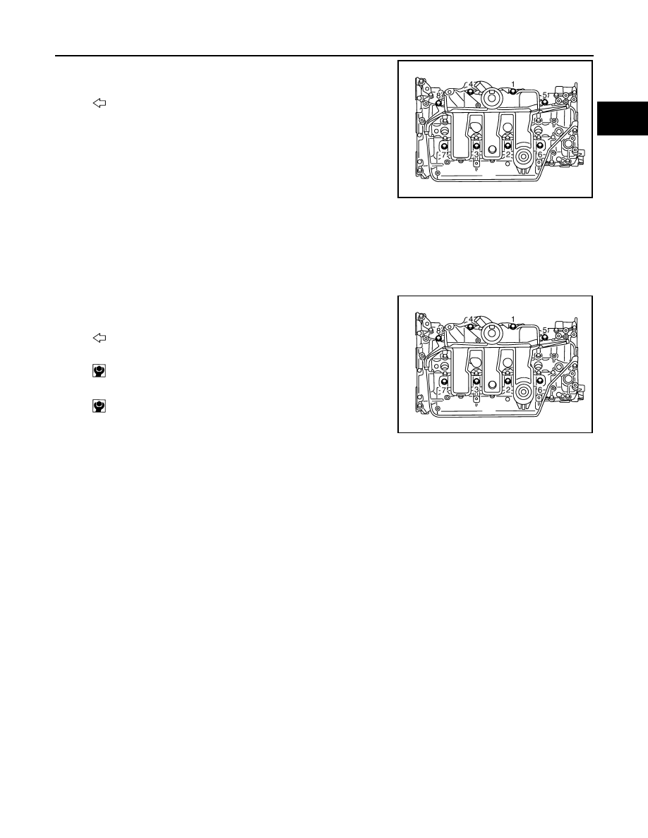
• Loosen mounting bolts in the reverse order as shown in the

figure.

6.

Remove oil separator insulator.

INSTALLATION

1.

Install gaskets to oil separator.

CAUTION:

Check the gasket is not dropped.

2.

Install oil separator. 
• Tighten mounting bolts in two steps separately in numerical

order as shown in the figure.

3.

Install in the reverse order of removal, for the rest of parts.

: Engine front

E1BIA0610ZZ

: Engine front

1st step: 5.0 N·m (0.51 kg-m, 44 in-lb)

2nd step: 10.0 N·m (1.0 kg-m, 7 ft-lb)

E1BIA0610ZZ

EM-404

< REMOVAL AND INSTALLATION >

[R9M]

INJECTION TUBE AND FUEL INJECTOR

INJECTION TUBE AND FUEL INJECTOR

Exploded View

INFOID:0000000010281997

Removal and Installation

INFOID:0000000010281998

REMOVAL

CAUTION:

• Be sure to read “Precautions for Diesel Equipment”. Refer to 

EM-364, "Precaution for Diesel Equip-

ment"

.

• Wait until the fuel temperature drops before carrying out any work.
• Order the special high pressure injection circuit plug kit.
• It is forbidden to open an fuel injector. If you open an fuel injector by mistake, you will have to

change it.

NOTE:
It is possible to replace a single injection tube.

1.

Oil separator

2.

Fuel injector spacer

3.

Injection tube (center) bolt

4.

Injection rail protector seal

5.

Cylinder head

6.

Fuel hose

7.

Fuel rail pressure sensor

8.

Injection rail protector seal

9.

Injection rail

10. injection rail bolts

11.

Bracket

12. Injection rail protector seal

13. Clip

14. Fuel hose

15. Fuel injector support bolt

16. Fuel return hose

17. Clip

18. Injector

19. Fuel injector support 

20. Injection tube

21. Injection tube (center)

22. Fuel hose

A.

Refer to 

EM-404, "Removal and In-

stallation"

B.

Refer to 

EM-404, "Removal and 

Installation"

C.

To fuel pump

Refer to 

GI-4, "Components"

 for symbols in the figure.

E1BIA1210GB

INJECTION TUBE AND FUEL INJECTOR

EM-405

< REMOVAL AND INSTALLATION >

[R9M]

C

D

E

F

G

H

I

J

K

L

M

A

EM

N

P

O

1.

Remove the battery. Refer to 

PG-155, "Removal and Installation"

.

2.

Remove oil separator. Refer to 

EM-402, "Exploded View"

.

3.

Remove fuel return hose.
• Move without removing the fuel return hose clip using a flate

bade screwdriver.

4.

Disconnect and remove fuel hose. 

5.

Remove fuel collector and injection tube (center).

6.

Remove injection tube (No. 1, 2, 3, 4).
• Put a paint mark or tag on injection tubes to identify each cylinder.

7.

Remove fuel injectors with the following procedure:

a.

Remove fuel injector. While rotating it to left and right, raise it to remove.
• If fuel injector spacer remains in cylinder head, hook it with tip of a flat-bladed screwdriver and pull it out.

CAUTION:

• Handle fuel injector carefully without giving an impact.
• Never disassemble fuel injector.

8.

Remove injection rail and injection rail protector.

9.

CAUTION:

In case of fuel rail pressure sensor fitted with a color ring: 
• replacing the sensor is forbidden
• the injector rail must be completely replaced if the fuel rail pressure sensor fails.

10. Plug all the holes in the injection circuit.

INSTALLATION

1.

If an injector is remplaced, not the IMA code and the corresponding cylinder number and perform "injector
adjustement value registration". Refer to 

EC9-147, "Work Procedure"

.

NOTE:
IMA code are from X1 to XN
After connecting the battery programs the injectors using the diagnostic tool.

2.

Install fuel injector, injection tubes and fuel rail with the following procedure:

a.

Install fuel injector spacer to fuel injector, and insert them into cylinder head.

E1BIA0648ZZ

E1BIA0649ZZ

EM-406

< REMOVAL AND INSTALLATION >

[R9M]

INJECTION TUBE AND FUEL INJECTOR

CAUTION:

• Completely remove any foreign material among fuel injector and cylinder head.

b.

Install injection rail, injection tube (center).
• Finger tighten until contact the injection tube nuts.

c.

Install fuel injector support.

CAUTION:

Be sure to fit fuel injector support without looseness.

d.

NOTE:
In case of cylinder head replacement, pre-tighten the fuel injector support bolt and after loosen the fuel
injector support bolt. 

Tighten fuel injector support bolt.

e.

Turn 180 degrees clockwise (angle tightening).

f.

Install injection tube (No. 1, 2, 3, 4) in the original position (temporarily).
• Finger tighten until contact the injection tube nuts.

CAUTION:

Never put injection tubes under stress.

g.

Tighten injection rail mounting bolts and all injection tube nuts (specified torque).

3.

Install fuel return hose onto fuel injectors with the following procedure.
• NOTE:

Failure to observe the following procedure may lead to an immobilising default.

• Fit the clip on the fuel return hose.
• Install fuel return hose onto fuel injectors.
• Always carry out a "push-pull" test (1), to check that the fuel

return hose is correctly fitted onto fuel injector.

• Always carry out a "push-pull" test, to check that the fuel return

hose is correctly fitted onto fuel hose.

4.

Install in the reverse order of removal, for the rest of parts.

Inspection

INFOID:0000000010281999

INSPECTION AFTER INSTALLATION

• When replacing fuel injector, this procedure must be performed. Refer to 

EC9-143, "Special Repair Require-

ment List"

• When replacing fuel injector, note the injector IMA code and the corresponding cylinder number.  

NOTE:
IMA codes are from X1 to XN.

- Program the injectors using diagnostic tool.

Pre- tightening fuel injec-
tor support bolt (in case of 
cylinder head replace-
ment)

20 Nm (2.0kg-m, 15 ft-lb)

Fuel injector support bolt

7Nm (0.7kg-m, 62 in-lb)

E1BIA0648ZZ


Content   ..  114  115  116  117   ..