Nissan Qashqai J11. Manual - part 91
ROCKER COVER
EM-303
< REMOVAL AND INSTALLATION >
[K9K]
C
D
E
F
G
H
I
J
K
L
M
A
EM
N
P
O
ROCKER COVER
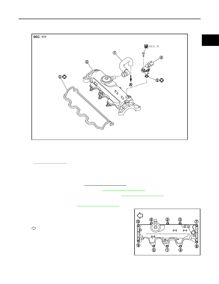
Exploded View
INFOID:0000000010287217
for symbol marks in the figure.
Removal and Installation
INFOID:0000000010287218
REMOVAL
1.
Remove air cleaner case. Refer to
2.
Remove inlet tube and air inlet hose. Refer to
3.
Remove high pressure protection cover (upper). Refer to
.
4.
Remove electric throttle control actuator.
5.
Remove fuel injector. Refer to
6.
Remove rocker cover.
• Loosen holding bolts in the reverse order as shown in the fig-
ure and remove.
INSTALLATION
E1BIA0908GB
1.
Blow-by hose
2.
Rocker cover
3.
Gasket
4.
Camshaft position sensor
5.
O-ring
A.
To turbocharger air inlet pipe
: Engine front
JPBIA3119ZZ