Nissan Qashqai J11. Manual - part 40


  Index      Nissan     Nissan Qashqai J11 - Service and Repair Manual


Search            


Content   ..  38  39  40  41   ..


Nissan Qashqai J11. Manual - part 40


CYLINDER BLOCK

EM-99

< UNIT DISASSEMBLY AND ASSEMBLY >

[HRA2DDT]

C

D

E

F

G

H

I

J

K

L

M

A

EM

N

P

O

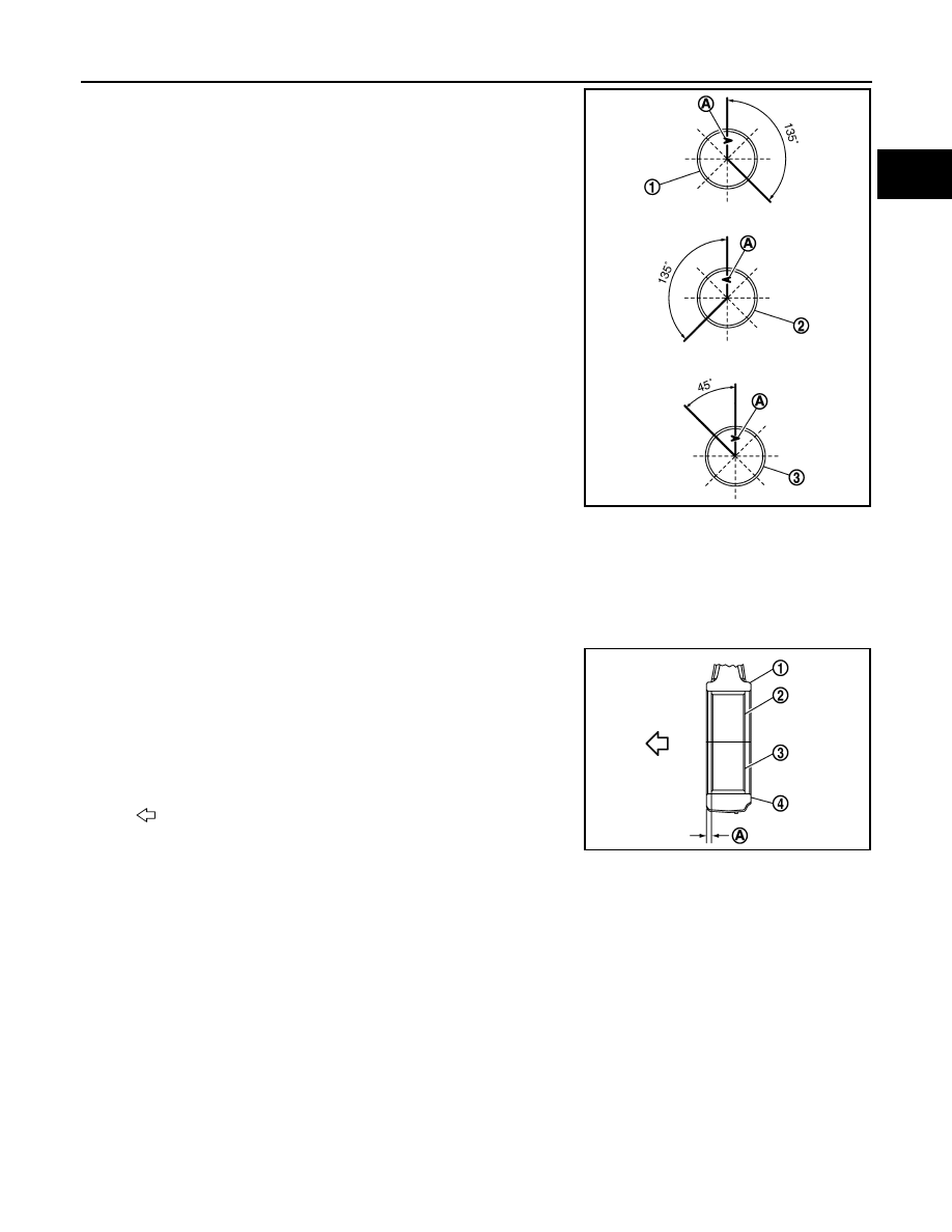
• Position the 3 parts oil ring with the end gap placed as shown

in the figure referring to the piston front mark (A).

9.

Install connecting rod bearings to connecting rod and connecting rod cap.
• When installing connecting rod bearings, apply new engine oil to the bearing surface (inside). Do not

apply engine oil to the back surface, but thoroughly clean it. 

• Install the bearing in the center position.

NOTE:
There is no stopper tab.

• Check that the oil holes on connecting rod and connecting rod bearing are aligned.
• Install the connecting rod in the dimension as shown in the fig-

ure.

NOTE:
Install the connecting rod bearing in the center position with
the dimension as shown in the figure. For service operation, the center position can be checked visually.

10. Install piston and connecting rod assembly to crankshaft. 

• Position crankshaft pin corresponding to connecting rod to be installed onto the bottom dead center. 
• Apply new engine oil sufficiently to the cylinder bore, piston and crankshaft pin. 
• Match the cylinder position with the cylinder number on connecting rod to install. 

1

: Upper rail

2

:  Spring

3

: Lower rail

E1BIA1108ZZ

1

: Connecting rod

2

: Connecting rod bearing (upper)

3

: Connecting rod bearing (lower)

4

: Connecting rod cap

A

: 2.05 - 2.07 mm (0.0807 - 0.0815 in)

: Engine front

PBIC4169E

EM-100

< UNIT DISASSEMBLY AND ASSEMBLY >

[HRA2DDT]

CYLINDER BLOCK

• Check that the piston mark (A) is facing towards timing chain

face.

• Using the piston ring compressor [SST: EM03470000] (B) or

suitable tool, install piston with the front mark on the piston
head facing the front of the engine. 

CAUTION:

• Be careful not to damage matching surface with con-

necting rod cap.

• Be careful not to damage the cylinder wall and crank-

shaft pin, resulting from an interference of the connect-
ing rod big end.

11. Install connecting rod cap. 

• Install connecting rod so that the front mark (A) on the piston

head is align with connecting rod mark as shown in the figure.  

12. Inspect outer diameter of connecting rod bolts. Refer to 

EM-102, "Inspection"

.

13. Tighten connecting rod bolt with the following procedure:
a.

Apply new engine oil to the threads and seats of connecting rod bolts. 

b.

Tighten bolts in several steps.

c.

Then turn all bolts 110 degrees clockwise (angle tightening).

CAUTION:

Check and confirm the tightening angle by using the angle
wrench [SST: KV10112100] (A) or protractor. Avoid judge-
ment by visual inspection without the tool.

E1BIA1108ZZ

PBIC3765E

E1BIA1105ZZ

: 25.0 N·m (2.6 kg-m, 18 ft-lb)

PBIC3753E

CYLINDER BLOCK

EM-101

< UNIT DISASSEMBLY AND ASSEMBLY >

[HRA2DDT]

C

D

E

F

G

H

I

J

K

L

M

A

EM

N

P

O

• After tightening connecting rod bolt, check that crankshaft rotates smoothly. 
• Check the connecting rod side clearance. Refer to 

EM-102, "Inspection"

.

14. Install main bearing beam with the following procedure.

a.

Install bolts.

b.

Tighten in numerical order as shown in the figure with the follow-
ing steps.

15. Install oil pan (upper). Refer to 

EM-89, "Exploded View"

.

NOTE:
Install the rear oil seal after installing the oil pan (upper).

16. Install rear oil seal. Refer to 

EM-87, "REAR OIL SEAL : Removal and Installation"

.

17. Install flywheel with the following procedure.
a.

Lock flywheel using [SST — (Mot.1431)], and tighten bolts.

CAUTION:

Be careful not to damage or scratch and contact surface for clutch disc of flywheel.

b.

Then turn all bolts 110 degrees clockwise (angle tightening).

CAUTION:

Check and confirm the tightening angle by using the angle wrench [SST: KV10112100] (A) or pro-
tractor. Avoid judgement by visual inspection without the tool.

18. Install knock sensor (1).

• Install connector so that they are positioned as shown in the

figure.

• Tighten knock sensor.

CAUTION:

• Never tighten mounting bolt while holding the connector.   
• If any impact by dropping is applied to knock sensor,

replace it with a new one.

NOTE:
• Check that there is no foreign material on the cylinder block mating surface and the back surface of

knock sensor. 

• Check that knock sensor does not interfere with other parts.

19. Install crankshaft position sensor (POS).

• Tighten crankshaft position sensor (POS).

20. When replacing crankshaft position sensor, this procedure must be performed. Refer to 

ECH-102, "Spe-

cial Repair Requirement List"

.

21. Assemble in the reverse order of disassembly after this step.

: 25.0 N·m (2.6 kg-m, 18 ft-lb)

E1BIA1068ZZ

: 32.0 N·m (3.3 kg-m, 24 ft-lb)

: Engine front

: 20.0 N·m (2.0 kg-m, 15 ft-lb)

: 8.0 N·m (0.8 kg-m, 71 in-lb)

E1BIA1110ZZ

EM-102

< UNIT DISASSEMBLY AND ASSEMBLY >

[HRA2DDT]

CYLINDER BLOCK

Inspection

INFOID:0000000010282252

CRANKSHAFT END PLAY

• Measure the clearance between thrust bearings and crankshaft

arm when crankshaft is moved fully forward or backward with a dial
indicator (A).

• If the measured value exceeds the limit, replace thrust bearings,

and measure again. If it still exceeds the limit, replace crankshaft
also.

CONNECTING ROD SIDE CLEARANCE

• Measure the side clearance between connecting rod and crank-

shaft arm with a feeler gauge (A).

• If the measured value exceeds the limit, replace connecting rod,

and measure again. If it still exceeds the limit, replace crankshaft
also.

PISTON TO PISTON PIN OIL CLEARANCE

Piston Pin Hole Diameter 

Measure the inner diameter of piston pin hole with an inside
micrometer (A).

Piston Pin Outer Diameter 

Measure the outer diameter of piston pin with a micrometer (A).

Piston to Piston Pin Oil Clearance

(Piston to piston pin oil clearance) = (Piston pin hole diameter) – (Piston pin outer diameter)

Standard and Limit

: Refer to 

EM-118, "Cylinder 

Block"

.

PBIC3762E

Standard and Limit

: Refer to 

EM-118, "Cylinder 

Block"

.

PBIC3763E

Standard

: Refer to 

EM-118, "Cylinder Block"

.

PBIC3265J

Standard : 

Refer 

to 

EM-118, "Cylinder Block"

.

PBIC3266J

Standard : 

Refer 

to 

EM-118, "Cylinder Block"

.


Content   ..  38  39  40  41   ..