Nissan Qashqai J11. Manual - part 38


  Index      Nissan     Nissan Qashqai J11 - Service and Repair Manual


Search            


Content   ..  36  37  38  39   ..


Nissan Qashqai J11. Manual - part 38


OIL PAN (UPPER)

EM-91

< UNIT DISASSEMBLY AND ASSEMBLY >

[HRA2DDT]

C

D

E

F

G

H

I

J

K

L

M

A

EM

N

P

O

c.

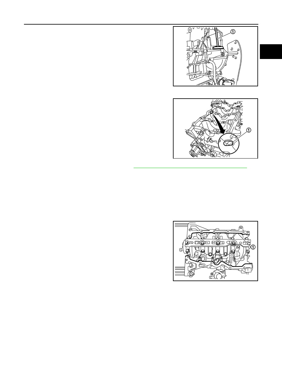
Insert the seal cutter [SST: KV10111100] (1) between the oil pan
(upper) and cylinder block. Slide seal cutter by tapping on the
side of tool with a hammer.

CAUTION:

• Be careful not to damage the mating surface.
• A more adhesive liquid gasket is applied compared to pre-

vious types when shipped, so it should not be forced off
using a screwdriver, etc. outside the indicated location.

d.

Remove oil pan (upper)

e.

Remove oil pan (upper) O-ring (1).

11. Remove rear oil seal from crankshaft. Refer to 

EM-87, "REAR OIL SEAL : Removal and Installation"

INSTALLATION

1.

Install the oil pan (upper) in the following procedure:

a.

Use scraper to remove old liquid gasket from mating surfaces.
• Also remove the old liquid gasket from mating surface of cylinder block.
• Remove old liquid gasket from the bolt holes and threads.

CAUTION:

Never scratch or damage the mating surfaces when cleaning off old liquid gasket.

b.

Install new oil pan (upper) oil seal.

c.

Apply a continuous bead of liquid gasket (1) with the tube
presser (commercial service tool) to areas as shown in the fig-
ure.
Use Genuine Liquid Gasket or equivalent.

CAUTION:

Attaching should be done within 5 minutes after coating.

E1BIA1047ZZ

E1BIA1048ZZ

Bead of liquid gasket diameter

φ

4.0 - 5.0 mm (0.157 - 0.197 in)

Distance from inside edge

: 7.5 - 9.5 mm (0.295 - 0.374 in)

E1BIA1049ZZ

EM-92

< UNIT DISASSEMBLY AND ASSEMBLY >

[HRA2DDT]

OIL PAN (UPPER)

d.

Tighten bolts in the numerical order as shown in the figure.

CAUTION:

Install avoiding misalignment of both oil pan gasket and O-
ring.
• The bolts are different according to the installation position.

CAUTION:

Take care to install correct size bolts for each position.

CAUTION:

Be sure to wipe off any excessive liquid gasket leaking to surface.

2.

Install rear oil seal. Refer to 

EM-87, "REAR OIL SEAL : Removal and Installation"

.

CAUTION:

• The installation of rear oil seal should be completed within 5 minutes after installing oil pan

(upper).

• Never touch oil seal lip.

3.

Install in the reverse order of removal, for the rest of parts.

Inspection

INFOID:0000000010282249

INSPECTION AFTER INSTALLATION

1.

Check engine oil level and adjust engine oil. Refer to 

LU-8, "Inspection"

.

2.

Check for leakage of engine oil when engine is warmed.

3.

Stop engine and wait for 10 minutes.

4.

Check engine oil level again. Refer to 

LU-8, "Inspection"

.

: Engine front

: 25.0 N·m (2.6 kg-m, 18 ft-lb)

E1BIA1050ZZ

CYLINDER BLOCK

EM-93

< UNIT DISASSEMBLY AND ASSEMBLY >

[HRA2DDT]

C

D

E

F

G

H

I

J

K

L

M

A

EM

N

P

O

CYLINDER BLOCK

Exploded View

INFOID:0000000010282250

Refer to 

GI-4, "Components"

 for symbols in the figure.

Disassembly and Assembly

INFOID:0000000010282251

DISASSEMBLY

NOTE:
Explained here is how to disassemble with an engine stand supporting mating surface of transaxle. When
using different type of engine stand, note with difference in steps and etc.

1.

Top ring

2.

Second ring

3.

Oil ring

4.

Piston 5.

Snap 

ring

6.

Piston 

pin

7.

Snap ring

8.

Oil jet

9.

Connecting rod bearing

10. Connecting rod

11.

Thrust bearing

12.

Crankshaft sprocket

13. Crankshaft

14.

Crankshaft rear oil seal 

15.

Dowel pin

16. Flywheel

17.

Main bearing cap

18.

Main bearing

19. Main bearing beam

A.

Tightening must be done following the assembly procedure.
Refer to 

EM-93, "Disassembly and Assembly"

E1BIA1020GB

EM-94

< UNIT DISASSEMBLY AND ASSEMBLY >

[HRA2DDT]

CYLINDER BLOCK

1.

Remove cylinder head. Refer to 

EM-69, "Exploded View"

.

2.

Remove knock sensor bolt (1) and knock sensor (2).

CAUTION:

Carefully handle knock sensor avoiding shocks.

3.

Remove crankshaft position sensor (POS) (1).

CAUTION:

• Avoid impacts such as a dropping.
• Never disassemble.
• Keep it away from metal particles.
• Never place the sensor in a location where it is exposed to

magnetism.

4.

Remove oil pan (upper and lower). Refer to 

EM-89, "Exploded View"

.

5.

Remove main bearing beam with the following procedure.

a.

Loosen and remove bolts in several steps in reverse of the
numerical order as shown in the figure.

6.

Remove piston and connecting rod assembly with the following procedure:
• Before removing piston and connecting rod assembly, check the connecting rod side clearance. Refer to

EM-102, "Inspection"

.

a.

Position crankshaft pin corresponding to connecting rod to be removed onto the bottom dead center. 

b.

Remove connecting rod cap. 

c.

Using a hammer handle or similar tool, push piston and connect-
ing rod assembly out to the cylinder head side. 

CAUTION:

• Be careful not to damage matching surface with connect-

ing rod cap.

• Be careful not to damage the cylinder wall and crankshaft

pin, resulting from an interference of the connecting rod
big end.

7.

Remove connecting rod bearings. 

CAUTION:

E1BIA1102ZZ

: Engine front

E1BIA1103ZZ

E1BIA1068ZZ

KBIA3365J


Content   ..  36  37  38  39   ..