Nissan Qashqai J11. Manual - part 36


  Index      Nissan     Nissan Qashqai J11 - Service and Repair Manual


Search            


Content   ..  34  35  36  37   ..


Nissan Qashqai J11. Manual - part 36


CAMSHAFT

EM-83

< UNIT DISASSEMBLY AND ASSEMBLY >

[HRA2DDT]

C

D

E

F

G

H

I

J

K

L

M

A

EM

N

P

O

• If it exceeds the limit, replace either or both camshaft and cylinder head.

NOTE:
Camshaft brackets cannot be replaced as single parts, because they are machined together with cylinder
head. Replace whole cylinder head assembly.
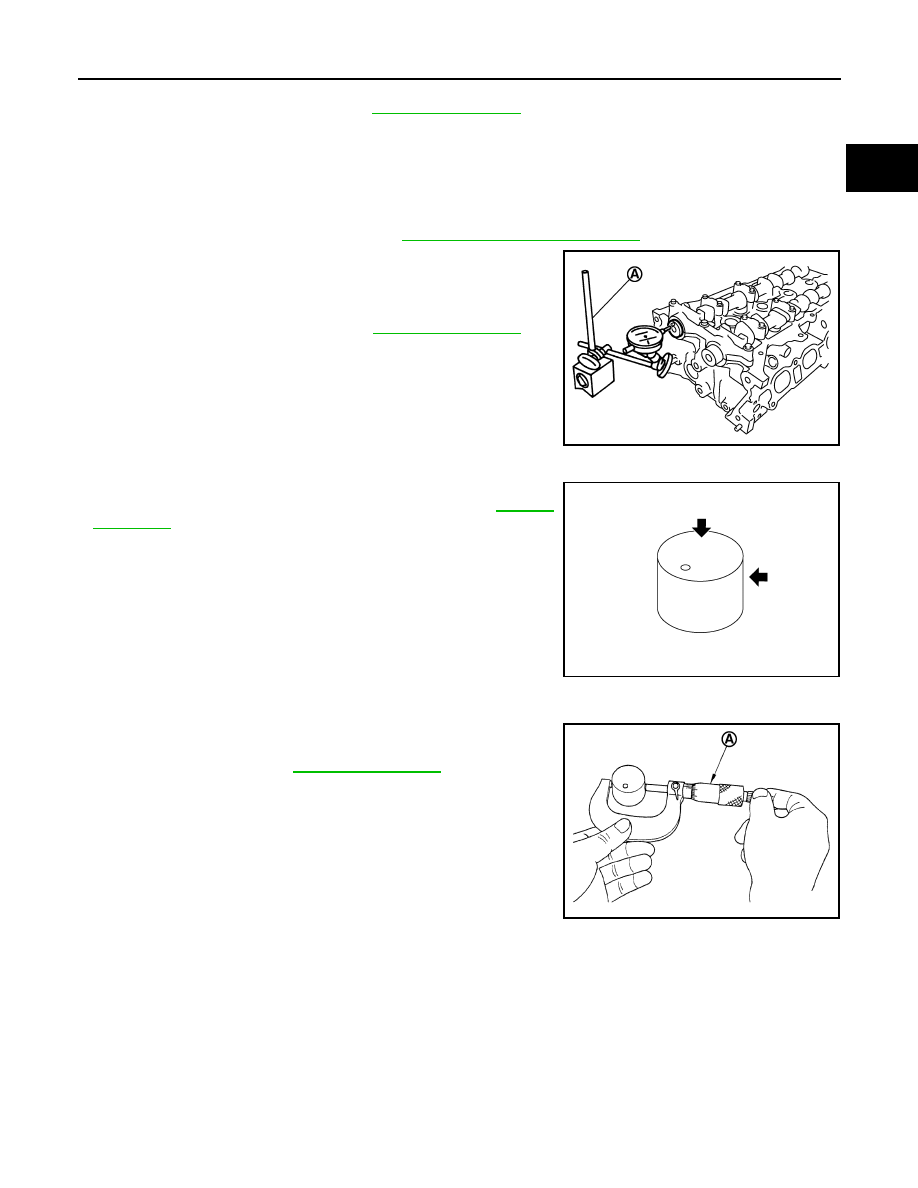
Camshaft End Play

1.

Install camshaft in cylinder head. Refer to 

EM-77, "Removal and Installation"

 for tightening procedure.

2.

Install a dial indicator (A) in thrust direction on front end of cam-
shaft. Measure the camshaft end play on the dial indicator when
camshaft is moved forward/backward (in direction to axis).

Valve Lifter 

Check if surface of valve lifter has any wear or cracks.
• If anything above is found, replace valve lifter. Refer to 

EM-114,

"Camshaft"

.

Valve Lifter Clearance

VALVE LIFTER OUTER DIAMETER
• Measure the outer diameter of valve lifter with a micrometer (A).

VALVE LIFTER HOLE DIAMETER

Standard and Limit

: Refer to 

EM-114, "Camshaft"

.

Standard and Limit

: Refer to 

EM-114, "Camshaft"

.

PBIC3694E

KBIA0182E

Standard

: Refer to 

EM-114, "Camshaft"

.

PBIC3185J

EM-84

< UNIT DISASSEMBLY AND ASSEMBLY >

[HRA2DDT]

CAMSHAFT

Measure the diameter of valve lifter hole of cylinder head with an
inside micrometer (A).

VALVE LIFTER CLEARANCE
• (Valve lifter clearance) = (Valve lifter hole diameter) – (Valve lifter outer diameter)

• If out of the standard, referring to the each standard of valve lifter outer diameter and valve lifter hole diame-

ter, replace either or both valve lifter and cylinder head.

INSPECTION AFTER INSTALLATION

Inspection for Leaks

The following are procedures for checking fluids leak, lubricates leak.

• Before starting engine, check oil/fluid levels including engine coolant and engine oil. If less than required

quantity, fill to the specified level. Refer to 

MA-59, "Fluids and Lubricants"

.

• Use procedure below to check for fuel leakage.
- Turn ignition switch “ON” (with engine stopped). With fuel pressure applied to fuel piping, check for fuel leak-

age at connection points.

- Start engine. With engine speed increased, check again for fuel leakage at connection points.
• Run engine to check for unusual noise and vibration.

NOTE:
If hydraulic pressure inside timing chain tensioner drops after removal/installation, slack in the guide may
generate a pounding noise during and just after engine start. However, this is normal. Noise will stop after
hydraulic pressure rises.

• Warm up engine thoroughly to check there is no leakage of fuel, or any oil/fluids including engine oil and

engine coolant.

• Bleed air from lines and hoses of applicable lines, such as in cooling system.
• After cooling down engine, again check oil/fluid levels including engine oil and engine coolant. Refill to the

specified level, if necessary.

Summary of the inspection items:

*: Power steering fluid, brake fluid, etc.

Inspection and Adjustment

INFOID:0000000010282208

INSPECTION

Perform inspection as follows after removal, installation or replacement of camshaft or valve-related parts, or if
there is unusual engine conditions regarding valve clearance. 

1.

Remove rocker cover. Refer to 

EM-49, "Exploded View"

.

Standard

: Refer to 

EM-114, "Camshaft"

.

PBIC3184J

Standard

: Refer to 

EM-114, "Camshaft"

.

Items

Before starting engine

Engine running

After engine stopped

Engine coolant

Level

Leakage

Level

Engine oil

Level

Leakage

Level

Transmission / 
transaxle fluid

AT & CVT Models

Leakage

Level / Leakage

Leakage

MT Models

Level / Leakage

Leakage

Level / Leakage

Other oils and fluids*

Level

Leakage

Level

Fuel

Leakage

Leakage

Leakage

Exhaust gases

Leakage

CAMSHAFT

EM-85

< UNIT DISASSEMBLY AND ASSEMBLY >

[HRA2DDT]

C

D

E

F

G

H

I

J

K

L

M

A

EM

N

P

O

2.

Measure the valve clearance with the following procedure:

a.

Set cam to be checked in the same position as shown in the figure.
• Rotate camshaft to set cam noses in the correct position.

b.

Use a feeler gauge (A), measure the clearance between valve
lifter and camshaft. 

3.

If out of standard, perform adjustment. Refer to “ADJUSTMENT”.

ADJUSTMENT

• Perform adjustment depending on selected head thickness of valve lifter.
1.

Remove camshaft. Refer to 

EM-77, "Exploded View"

.

2.

Remove valve lifters at the locations that are out of the standard.

3.

Measure the center thickness of the removed valve lifters with a
micrometer (A).

4.

Use the equation below to calculate valve lifter thickness for replacement.

A : Cam noses facing upward

E1BIA1097ZZ

Valve clearance

: Refer to 

EM-84, "Inspection and Ad-

justment"

.

E1BIA1098ZZ

PBIC3195J

Valve lifter thickness calculation:

t = t

1

 + (C

– C

2

)

t

= Valve lifter thickness to be replaced

t

1

= Removed valve lifter thickness

C

1

= Measured valve clearance

C

2

= Standard valve clearance:

Intake

: 0.30 mm (0.012 in)

Exhaust

: 0.50 mm (0.020 in)

EM-86

< UNIT DISASSEMBLY AND ASSEMBLY >

[HRA2DDT]

CAMSHAFT

• Thickness of new valve lifter (A) can be identified by stamp

mark (B) on the reverse side (inside the cylinder).

• Stamp mark “302” indicates 3.02 mm (0.1189 in) in thickness.

NOTE:
Available thickness of valve lifter: 31 sizes range 2.96 to 3.56 mm (0.1165 to 0.1402 in) in steps of 0.02
mm (0.0008 in) (when manufactured at factory). Refer to 

EM-114, "Camshaft"

.

5.

Install the selected valve lifter.

6.

Install camshaft. Refer to 

EM-77, "Exploded View"

.

7.

Install timing chain and related parts. Refer to 

EM-58, "Exploded View"

.

8.

Manually rotate crankshaft pulley a few rotations. 

9.

Check that the valve clearances is within the standard. Refer to “

EM-84, "Inspection and Adjustment"

”.

10. Install remaining parts in the reverse order of removal.

11. Warm up the engine, and check for unusual noise and vibration.

E1BIA1099ZZ


Content   ..  34  35  36  37   ..