Nissan Qashqai J11. Manual - part 28
IGNITION COIL, SPARK PLUG AND ROCKER COVER
EM-51
< REMOVAL AND INSTALLATION >
[HRA2DDT]
C
D
E
F
G
H
I
J
K
L
M
A
EM
N
P
O
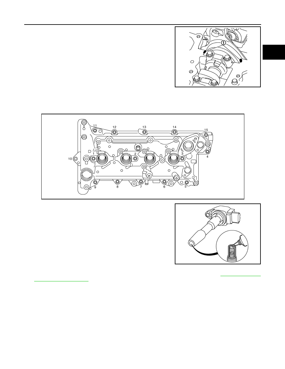
a.
Apply liquid gasket to the position (1) as shown in the figure.
Use Genuine Liquid Gasket or equivalent.
b.
Install rocker cover to cylinder head.
CAUTION:
Check the gasket is not dropped.
• Tighten bolts in two steps separately in numerical order as shown in the figure.
2.
Apply a bead of grease of 2 mm (0.08 in) diameter on the inter-
nal perimeter of the coil as shown in the figure.
3.
When replacing camshaft position sensor, this precedure must be performed. Refer to
4.
Install in the reverse order of removal, for the rest of parts.
1
: Cylinder head
2
: Front cover
a
:
φ
2.5 - 3.5 mm (0.10 - 0.14 in)
E1BIA1031ZZ
E1BIA1030ZZ
E1BIA1025ZZ