Nissan Qashqai J11. Manual - part 26


  Index      Nissan     Nissan Qashqai J11 - Service and Repair Manual


Search            


Content   ..  24  25  26  27   ..


Nissan Qashqai J11. Manual - part 26


FUEL INJECTOR AND FUEL TUBE

EM-43

< REMOVAL AND INSTALLATION >

[HRA2DDT]

C

D

E

F

G

H

I

J

K

L

M

A

EM

N

P

O

6.

Disconnect:
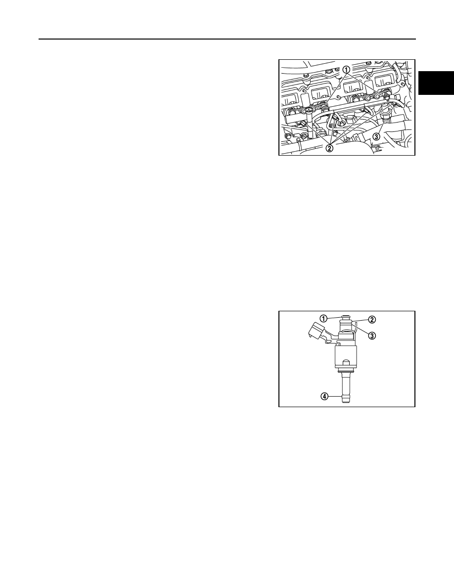
• Fuel injector connectors (2).
• Fuel pressure sensor connector (3) 

7.

Remove fuel tube and fuel injector assembly.

CAUTION:

• When removing, be careful to avoid any interference with fuel injector.
• Use a shop cloth to absorb any fuel leakage from fuel tube.
• Never reuse fuel tube.

8.

Remove fuel injector from fuel tube with the following procedure:

a.

Remove injector holder.

b.

Remove fuel injector by pulling straight.

CAUTION:

• Be careful with remaining fuel that may go out from fuel tube.
• Be careful not to damage fuel injector nozzle during removal.
• Never bump or drop fuel injector.

Fuel injector seal disassembly.

1.

Remove carefully from fuel injector:
• O-ring seal (1).
• O-ring lower seal (2).
• ring stopper (3).

CAUTION:

• Handle O-ring with bare hands. Never wear gloves.
• Lubricate O-ring with new engine oil.
• Never clean O-ring with solvent.
• Check that O-ring and its mating part are free of foreign

material.

• When installing O-ring, be careful not to scratch it with

tool or fingernails. Also be careful not to twist or stretch
O-ring. If O-ring is stretched while installing, never insert it quickly into fuel tube.

• Insert O-ring straight into fuel tube. Never decenter or twist it.

2.

Remove carefully from fuel injector teflon ring seal (4) following this procedure.
• Clean fuel injector

CAUTION:

It is forbidden to use a wire brush, sandpaper, etc.

• Cut fuel injector teflon ring seal with a pliers circlip.

CAUTION:

Take care to not damage fuel injector nozzle.

INSTALLATION

Fuel injector seal assembly.

E1BIA1166ZZ

E1BIA1167ZZ

EM-44

< REMOVAL AND INSTALLATION >

[HRA2DDT]

FUEL INJECTOR AND FUEL TUBE

1.

Install on fuel injector: 
• O-ring seal (1).
• O-ring lower seal (2).
• ring stopper (3).

CAUTION:

• Handle O-ring with bare hands. Never wear gloves.
• Lubricate O-ring with new engine oil.
• Never clean O-ring with solvent.
• Check that O-ring and its mating part are free of foreign

material.

• When installing O-ring, be careful not to scratch it with

tool or fingernails. Also be careful not to twist or stretch
O-ring. If O-ring is stretched while installing, never insert it quickly into fuel tube.

• Insert O-ring straight into fuel tube. Never decenter or twist it.

2.

Install carefully on fuel injector teflon ring seal (4) following this procedure using [SST: Mot.1533 (—)].
• Install on the fuel injector the cone (1) of [SST: Mot.1533 (—)]. 
• Install teflon ring seal on the cone (1) of [SST: Mot.1533 (—)].
• Push teflon ring seal into fuel injector groove.
• Remove the cone (1) of [SST: Mot.1533 (—)].

• Push the reforming tool (1) of [SST: Mot.1533 (—)] around fuel

injector nozzle to retract teflon ring seal during 30 secondes
minimum.
NOTE:
This operation is necessary to set correct outside diameter to
teflon ring seal.

Fuel injector and fuel tube installation.

CAUTION:

Never reuse fuel tube.

1.

Install fuel injector to fuel tube.

2.

Set fuel tube and fuel injector assembly at its position for installation on cylinder head.

CAUTION:

For installation, be careful not to interfere with fuel injector nozzle.

3.

Install fuel tube and injector assembly onto cylinder.
• Tighten mounting bolts.

4.

Connect harness connector to fuel injector.

5.

When replacing fuel injector, this procedure must be performed. Refer to 

ECH-102, "Special Repair

Requirement List"

.

6.

Install remaining parts in the reverse order of removal.

Inspection

INFOID:0000000010282222

INSPECTION AFTER INSTALLATION

E1BIA1167ZZ

E1BIA1168ZZ

E1BIA1169ZZ

FUEL INJECTOR AND FUEL TUBE

EM-45

< REMOVAL AND INSTALLATION >

[HRA2DDT]

C

D

E

F

G

H

I

J

K

L

M

A

EM

N

P

O

Check on Fuel Leakage

1.

Turn ignition switch “ON” (with the engine stopped). With fuel pressure applied to fuel piping, check there
are no fuel leakage at connection points.
NOTE:
Use mirrors for checking at points out of clear sight.

2.

Start the engine. With engine speed increased, check again that there are no fuel leakage at connection
points.

CAUTION:

Never touch the engine immediately after stopped, as the engine becomes extremely hot.

EM-46

< REMOVAL AND INSTALLATION >

[HRA2DDT]

OIL PAN (LOWER)

OIL PAN (LOWER)

Exploded View

INFOID:0000000010282223

Refer to 

GI-4, "Components"

 for symbol marks in the figure.

Removal and Installation

INFOID:0000000010282224

REMOVAL

1.

Drain engine oil. Refer to 

LU-9, "Draining"

.

2.

Remove oil pan (lower) with the following procedure:

1.

Dowel pin 

2.

Cylinder block

3.

Baffle plate

4.

Dowel pin

5.

Oil pan (upper)

6.

Oil pan (lower)

7.

Drain plug washer

8.

Drain plug 

E1BIA1015GB


Content   ..  24  25  26  27   ..