Nissan Qashqai J11. Manual - part 25


  Index      Nissan     Nissan Qashqai J11 - Service and Repair Manual


Search            


Content   ..  23  24  25  26   ..


Nissan Qashqai J11. Manual - part 25


HIGH PRESSURE FUEL PUMP AND FUEL HOSE

EM-39

< REMOVAL AND INSTALLATION >

[HRA2DDT]

C

D

E

F

G

H

I

J

K

L

M

A

EM

N

P

O

a.

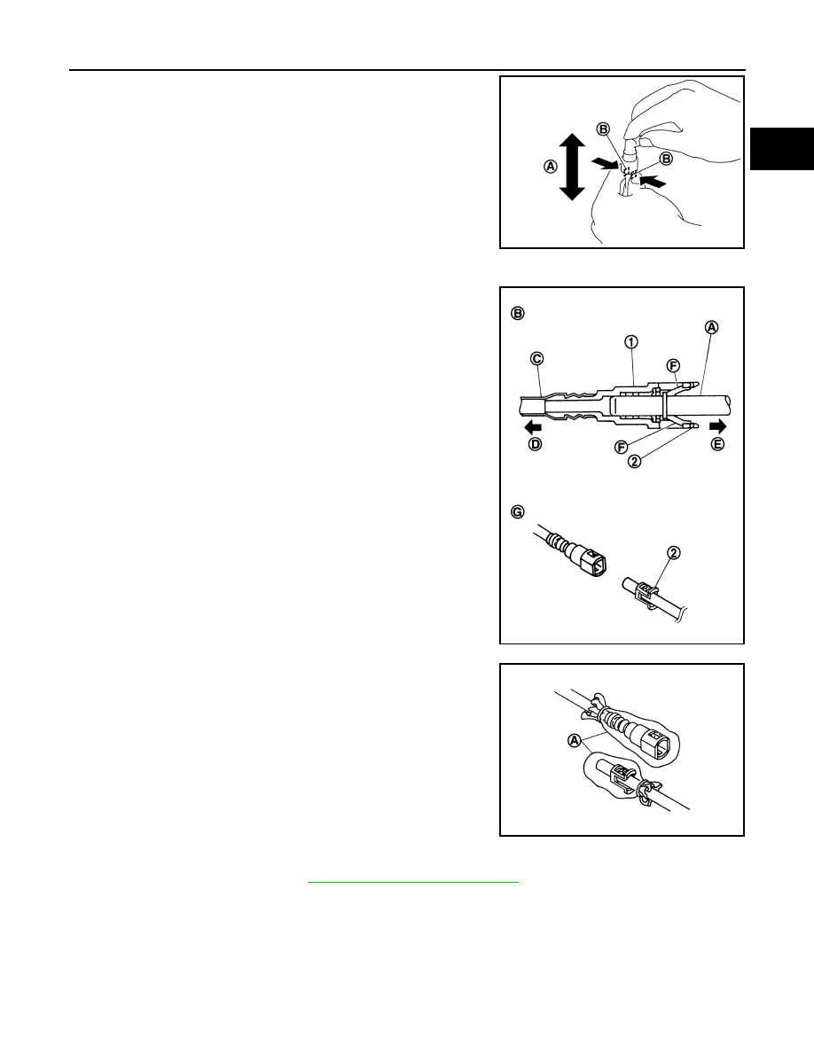
Remove quick connector in the following procedures.

i.

Hold the connector while pushing tabs, and pull out the tube.

ii.

If quick connector sticks to high pressure fuel pump, push and
pull quick connectors several times until they start to move.
Then disconnect them by pulling.

CAUTION:

• Quick connector (1) can be disconnected when the tabs of

retainer (F) are depressed completely. Never twist it more
than necessary.

• Never use any tools to disconnected quick connector.
• Keep resin hose (C) away from heat. Be especially careful

when welding near the resin hose.

• Prevent acid liquid such as battery electrolyte, etc. from

getting on resin tube.

• Never bend or twist resin tube during installation and dis-

connection.

• Never remove the remaining retainer (2) on hard tube (or

the equivalent) (A) except when resin tube or retainer is
replaced.

• When resin tube or hard tube (or the equivalent) is

replaced, also replace retainer with new one.

• To prevent damage to each joint and protect it from the

entry of foreign matter, cover the joint with plastic bag (A)
or an equivalent.

4.

Disconnect high pressure fuel pump connector.

5.

Remove intake manifold. Refer to 

EM-25, "Removal and Installation"

.

6.

Remove high pressure fuel pipe using [SST: KV113E0010 (Mot.1566)].

7.

Remove high pressure fuel pump and lifter.

CAUTION:

To prevent damage to high pressure fuel pump and rocker cover, loosen high pressure fuel pump
bolts alternately by one turn at a time until the reaction force applied on the high pressure fuel
pump disappears.

INSTALLATION

A

:  Pull

B

: Push in tabs

JSBIA1689ZZ

B

: Connection (cross-section)

D

: To under floor fuel line

E

: To engine

G

: Disconnection

Retainer color

: Green

JPBIA0130ZZ

JPBIA0135ZZ

EM-40

< REMOVAL AND INSTALLATION >

[HRA2DDT]

HIGH PRESSURE FUEL PUMP AND FUEL HOSE

CAUTION:

• Do not reuse O-rings.
• To prevent damage to parts due to generated abnormal stress and eccentric load, always observe

the installation procedure.

1.

Install high pressure pump lifter in its housing.

2.

Install high pressure fuel pump according to the following procedure.

a.

Check that high pressure fuel pump lifter (1) is in low position.
NOTE:
If the high pressure fuel pump lifter is not in low position turn the
engine by hand until reach high pressure fuel pump lifter low
position.

b.

c.

Install O-ring to high pressure fuel pump. When handing new O-ring, paying attention to the following cau-
tion items:

CAUTION:

• Do not reuse O-ring.
• Handle O-ring with bare hands. Never wear gloves.
• Lubricate O-ring with new engine oil.
• Never clean O-ring with solvent.
• Check that O-ring and its mating part are free of foreign material.
• Never damage O-ring with tools and fingernails during the installation. In addition, twisting or

stretching O-ring is not allowed. If O-ring is stretched during the installation to high pressure
fuel pump, never install high pressure fuel pump immediately.

d.

Install high pressure fuel pump lifter.

e.

Apply oil to the fitting area of O-ring and rocker cover side to install high pressure fuel pump.

CAUTION:

• Temporarily tighten bolt by hand. Alternately tighten bolt by one turn at a time until high pres-

sure fuel pump reaches rocker cover.

• After a pump flange sitting, tighten the bolts to the specified torque.

3.

Install the fuel tube, according to the following procedure using [SST: KV113E0010 (Mot.1566)].

CAUTION:

• When removing Fuel tube, always replace Fuel rail connector together with Fuel tube.
• Never reuse fuel tube.
• Never use fuel tube if its terminal tip is damaged.
• Observe the tightening order and the tightening torque.

a.

Temporarily tighten flare nut (A) and (B) of fuel tube (3) until
seated.

CAUTION:

When temporarily tightening flare nut, place pipe in the cen-
ter of the nut inner diameter.

b.

Tighten bolt (4).

c.

Tighten flare nut (A) and (B) in alphabetical order.

CAUTION:

Always fit the tool completely with the nut.

E1BIA1164ZZ

1

: High pressure fuel pump

2

: Fuel rail connector

E1BIA1165ZZ

HIGH PRESSURE FUEL PUMP AND FUEL HOSE

EM-41

< REMOVAL AND INSTALLATION >

[HRA2DDT]

C

D

E

F

G

H

I

J

K

L

M

A

EM

N

P

O

4.

Connect fuel feed hose with the following procedure, and them install the fuel feed hose.

a.

Check the connection for damage or any foreign materials.

b.

Align the connector with the tube, then insert the connector straight into the tube until a click sound is
heard.

c.

After connecting, check that the connection is secured with fol-
lowing procedures.
• Visually confirm that the two tabs are connected to the con-

nector.

• Pull (A) the tube and the connector to check that they are

securely connected.

CAUTION:

If retainer cannot be installed smoothly, quick connector
may be have not been installed correctly. Check connection
again.

5.

When replacing high pressure fuel pump, this procedure must be perform. Refer to 

ECH-102, "Special

Repair Requirement List"

6.

Install in the reverse order of removal after this step.

Inspection

INFOID:0000000010287266

INSPECTION AFTER INSTALLATION

Check for Fuel Leakage

1.

Turn ignition switch “ON” (with the engine stopped). With fuel pressure applied to fuel piping, check that
there is no fuel leakage at connection points.
NOTE:
Use mirrors for checking at points out of clear sight.

2.

Start the engine. With engine speed increased, check again that there is no fuel leakage at connection
points.

CAUTION:

Never touch the engine immediately after it is stopped because the engine is extremely hot.

JSBIA1692ZZ

EM-42

< REMOVAL AND INSTALLATION >

[HRA2DDT]

FUEL INJECTOR AND FUEL TUBE

FUEL INJECTOR AND FUEL TUBE

Exploded View

INFOID:0000000010282220

Refer to 

GI-4, "Components"

 for symbols in the figure.

CAUTION:

Never remove or disassemble parts unless instructed as shown in the figure.

Removal and Installation

INFOID:0000000010282221

WARNING:

• Put a “CAUTION: FLAMMABLE” sign in the workshop.
• Be sure to work in a well ventilated area and furnish workshop with a CO

2

 fire extinguisher. 

• Never smoke while servicing fuel system. Keep open flames and sparks away from the work area.

REMOVAL

Fuel injector and fuel tube removal.

1.

Release the fuel pressure. Refer to 

ECH-121, "Work Procedure"

.

2.

Remove blow off valve. Refer to 

EM-27, "Removal and Installation"

3.

Remove intake manifold. Refer to 

EM-25, "Exploded View"

.

4.

Remove high pressure fuel pipe. Refer to 

EM-38, "Exploded View"

5.

Unclip injection harness (1) from fuel tube.

1.

Fuel tube

2.

O-ring seal

3.

O-ring lower seal

4.

Ring stopper

5.

Holder

6.

Fuel Injector

7.

Seal ring

8.

Fuel pressure sensor

9.

Teflon ring seal

E1BIA1012GB


Content   ..  23  24  25  26   ..