Nissan Juke F15. Manual - part 998
MWI-14
< SYSTEM DESCRIPTION >
SYSTEM
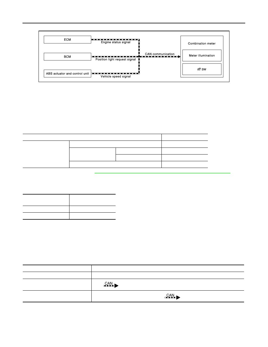
METER ILLUMINATION CONTROL : System Diagram
INFOID:0000000012201306
METER ILLUMINATION CONTROL : System Description
INFOID:0000000012201307
METER ILLUMINATION CONTROL FUNCTION
• Combination meter controls meter illumination, based on the following signal.
- Position light request signal
• The combination meter switches mode between Daytime mode and Nighttime mode, according to the fol-
lowing conditions.
*: For further information, refer to
INL-9, "ILLUMINATION CONTROL SYSTEM : System Description"
.
BUCK LIGHT ILLUMINATION CONTROL FUNCTION
The operation of the illumination control switch allows the brightness adjustment of meter illumination.
METER ILLUMINATION ON/OFF CONTROL FUNCTION
• Combination meter turns ON meter illumination when the following condition is satisfied:
- Ignition switch ON
• Combination meter turns OFF meter illumination when any of the following condition is satisfied:
- During a crank with vehicle speed less than 1 km/h (0.6 MPH) and ACC power supply OFF
- Ignition switch OFF or ACC power supply OFF
• The combination meter receives the following signals to control meter illumination.
METER EFFECT FUNCTION
JSNIA3378GB
Condition
Meter illumination
Combination switch
(lighting switch)
1ST or 2ND position
Nighttime mode
AUTO POSITION
Outdoor: Bright*
Daytime mode
Outdoor: Dark*
Nighttime mode
Off
Daytime mode
Meter illumination
The number of adjustable
steps
Daytime
12 step
Nighttime
12 step
Signal name
Signal path
Ignition signal
—
Engine status signal
ECM
Combination meter
Vehicle speed signal
ABS actuator and control unit (control unit)
Combination meter