Nissan Juke F15. Manual - part 997


  Index      Nissan     Nissan Juke F15 (2015 year) - Service and Repair Manual


Search            


Content   ..  995  996  997  998   ..


Nissan Juke F15. Manual - part 997


MWI-10

< SYSTEM DESCRIPTION >

SYSTEM

METER SYSTEM : Fail-Safe

INFOID:0000000012839331

FAIL-SAFE

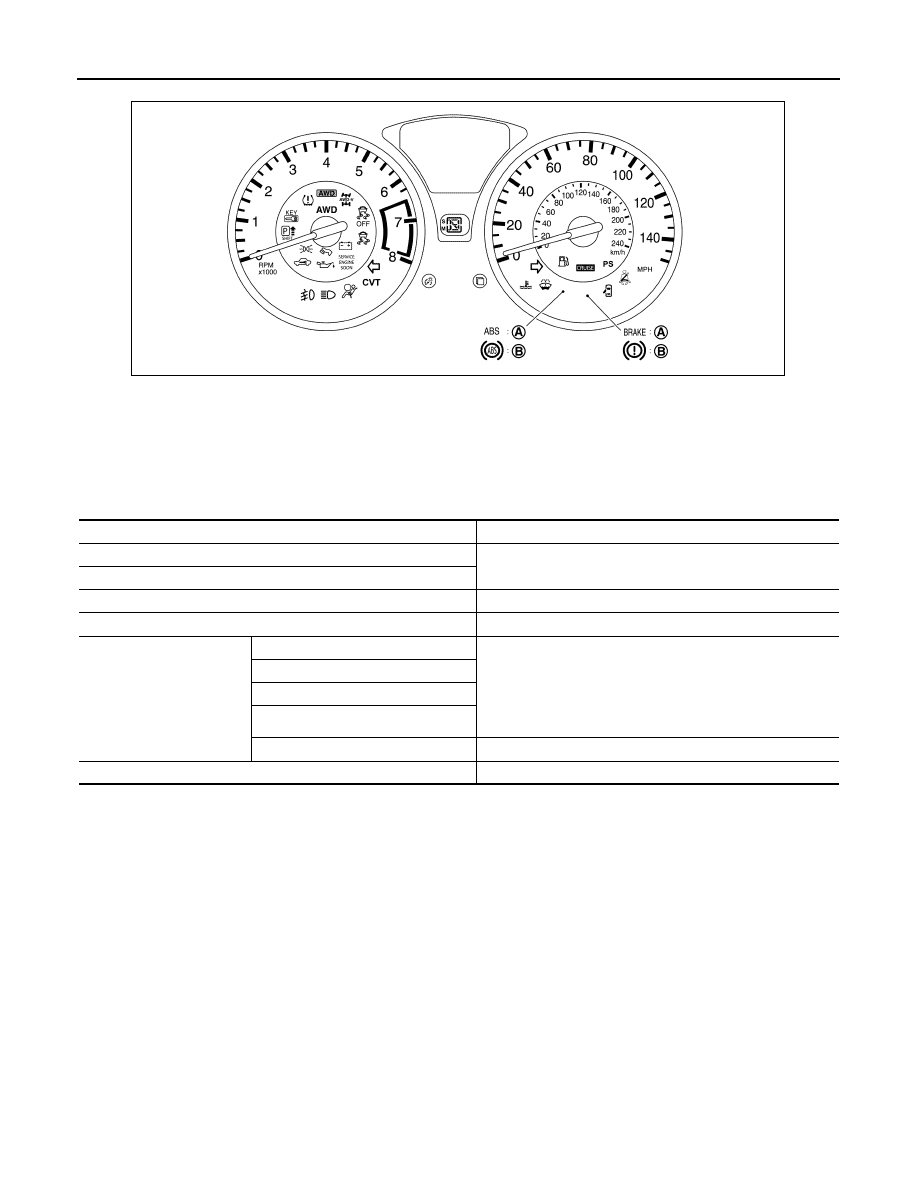
The combination meter activates the fail-safe control if CAN communication with each unit is malfunctioning.

A.

For U.S.A.

B.

For Canada

JSNIA8950ZZ

Function

Specifications

Speedometer

Reset to zero by suspending communication.

Tachometer

Illumination control

When suspending communication, changes to nighttime mode.

Shift position indicator

When suspending communication, not indicate.

Information display

Instantaneous fuel consumption

• When reception time of an abnormal signal is 2 seconds or 

less, the last received datum is used for calculation to indi-
cate the result.

• When reception time of an abnormal signal is more than two 

seconds, the last result calculated during normal condition is 
indicated.

Average fuel consumption

Possible driving distance

Torque distribution indicator

Low tire pressure warning

The display turns OFF by suspending communication.

Buzzer

The buzzer turns OFF by suspending communication.

MWI

SYSTEM

MWI-11

< SYSTEM DESCRIPTION >

C

D

E

F

G

H

I

J

K

L

M

B

A

O

P

SPEEDOMETER
SPEEDOMETER : System Diagram

INFOID:0000000012201298

SPEEDOMETER : System Description

INFOID:0000000012201299

• The ABS actuator and electric unit (control unit) converts the rectangular wave signal provided by the wheel

sensor to a vehicle speed signal and transmits it to the combination meter via CAN communication. 

• The combination meter indicates the vehicle speed to the speedometer according to the vehicle speed sig-

nal received via CAN communication. 

TACHOMETER

Warning lamp/indicator lamp

ABS warning lamp

The lamp turns ON by suspending communication.

Malfunction indicator lamp

VDC warning lamp

EPS warning lamp

AWD warning lamp

Brake warning lamp

VDC OFF indicator lamp

The lamp turns OFF by suspending communication.

High beam indicator lamp

Turn signal indicator lamp

Door warning lamp

Tail lamp indicator lamp

Engine start operation indicator lamp

Shift P warning lamp

Front fog lamp indicator lamp

Oil pressure warning lamp

CRUISE indicator lamp

AWD mode indicator lamp (AWD)

AWD mode indicator lamp (AWD-V)

Key warning lamp

CVT indicator lamp

Low tire pressure warning lamp

After blinking for 1 minute, the lamp remains ON.

High coolant temperature indicator 
lamp

When reception time of an abnormal signal is more than 60 
seconds, the lamp turns OFF.

Function

Specifications

JSNIA2973GB

MWI-12

< SYSTEM DESCRIPTION >

SYSTEM

TACHOMETER : System Diagram

INFOID:0000000012201300

CVT models

M/T models

TACHOMETER : System Description

INFOID:0000000012201301

CVT models

• ECM converts the pulse signal provided by the crankshaft position sensor to an engine speed signal and

transmits it to the TCM via CAN communication.

• TCM transmits the engine speed signal received from ECM via CAN communication to the combination

meter via CAN communication.

• The combination meter indicates the engine speed to the tachometer according to the engine speed signal

received via CAN communication. 

M/T models

• ECM converts the pulse signal provided by the crankshaft position sensor to an engine speed signal and

transmits it to the combination meter via CAN communication.

• The combination meter indicates the engine speed to the tachometer according to the engine speed signal

received via CAN communication. 

SHIFT POSITION INDICATOR
SHIFT POSITION INDICATOR : System Diagram

INFOID:0000000012201302

JSNIA7198GB

JSNIA2974GB

JSNIA6671GB

MWI

SYSTEM

MWI-13

< SYSTEM DESCRIPTION >

C

D

E

F

G

H

I

J

K

L

M

B

A

O

P

SHIFT POSITION INDICATOR : System Description

INFOID:0000000012201303

The combination meter receives the shift position signal from TCM via CAN communication, and displays the

shift position to the shift position indicator.

MANUAL MODE

When operated with CVT shift selector

• The combination meter receives the manual mode signal, non-manual mode signal, manual mode shift up

signal, and manual mode shift down signal from CVT shift selector and transmits them to TCM via CAN com-

munication. 

• TCM recognizes the manual mode operation status according to the manual mode signal, non-manual mode

signal, manual mode shift up signal, and manual mode shift down signal received via CAN communication

and transmits the manual mode indicator signal to the combination meter via CAN communication. 

• The combination meter indicates shift position according to the shift position signal received via CAN com-

munication. 

When operated with paddle shifter

• The combination meter receives the manual mode signal from CVT shift selector, paddle shifter up signal

and paddle shifter down signal from paddle shifter and transmits them to TCM via CAN communication.

• TCM recognizes the manual mode operation status according to the manual mode signal, manual mode

shift up signal, and manual mode shift down signal received via CAN communication and transmits the shift

position signal to the combination meter via CAN communication.

• The combination meter indicates shift position according to the shift position signal via CAN communication.

NON-MANUAL MODE

• TCM transmits the shift position signal to the combination meter via CAN communication. 

• The combination meter indicates shift position according to the shift position signal received via CAN com-

munication. 

SHIFT REFUSAL WARNING AND ALARM

• TCM sends a manual mode shift refusal signal to the combination meter via CAN communication when shift-

up and shift-down can not be operated in manual mode.

• The combination meter blinks the shift position indicator and sounds a buzzer according to a manual mode

shift refusal signal received via CAN communication.

OIL PRESSURE WARNING LAMP
OIL PRESSURE WARNING LAMP : System Diagram

INFOID:0000000012201304

OIL PRESSURE WARNING LAMP : System Description

INFOID:0000000012201305

The combination meter turns the oil pressure warning lamp ON when receiving ECM to the oil pressure warn-

ing lamp signal via CAN communication. For details, refer to 

EC-45, "Oil Pressure Warning Lamp"

 (MR for

NISMO RS models) or 

EC-619, "Oil Pressure Warning Lamp"

 (MR except for NISMO RS models).

METER ILLUMINATION CONTROL

JSNIA3115GB


Content   ..  995  996  997  998   ..