Nissan Juke F15. Manual - part 972


  Index      Nissan     Nissan Juke F15 (2015 year) - Service and Repair Manual


Search            


Content   ..  970  971  972  973   ..


Nissan Juke F15. Manual - part 972


LU-18

< UNIT DISASSEMBLY AND ASSEMBLY >

[MR FOR NISMO RS MODELS]

OIL PUMP

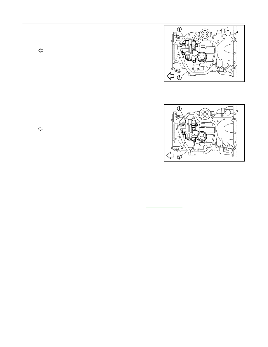
• Loosen bolts in reverse order as shown in the figure.

INSTALLATION

Note the following, and install in the reverse order of removal.

Oil Pump

• Tighten bolts in numerical order as shown in the figure.

Inspection

INFOID:0000000012197482

INSPECTION AFTER INSTALLATION

1. Check the engine oil level. Refer to 

LU-9, "Inspection"

.

2. Start the engine, and check that there is no leakage of engine oil.
3. Stop the engine and wait for 10 minutes.
4. Check the engine oil level, and adjust the level. Refer to 

LU-9, "Inspection"

.

1

: Oil pump

2

: Oil pan (upper)

: Engine front

JPBIA4451ZZ

1

: Oil pump

2

: Oil pan (upper)

: Engine front

JPBIA4451ZZ

SERVICE DATA AND SPECIFICATIONS (SDS)

LU-19

< SERVICE DATA AND SPECIFICATIONS (SDS) 

[MR FOR NISMO RS MODELS]

C

D

E

F

G

H

I

J

K

L

M

A

LU

N

P

O

SERVICE DATA AND SPECIFICATIONS (SDS)

SERVICE DATA AND SPECIFICATIONS (SDS)

Periodical Maintenance Specification

INFOID:0000000012197483

ENGINE OIL CAPACITY (APPROXIMATE)

Unit:   (US qt, lmp qt)

Engine Oil Pressure

INFOID:0000000012197484

Unit: kPa (kg/cm

2

, psi)

*: Engine oil temperature at 80

°C (176°F)

Drain and refill 

With oil filter change

4.5 (4-6/8, 4)

Without oil filter change

4.3 (4-4/8, 3-6/8)

Dry engine (Overhaul)

5.4 (5-6/8, 4-6/8)

Engine speed

Approximate discharge pressure*

Idle speed

90 (0.92, 13.1)

2,000 rpm

260 (2.65, 37.7) 

LU-20

< PRECAUTION >

[MR EXCEPT FOR NISMO RS MODELS]

PRECAUTIONS

PRECAUTION

PRECAUTIONS

Precautions for Removing Battery Terminal

INFOID:0000000012958963

When disconnecting the battery terminal, pay attention to the following.

• Always use a 12V battery as power source.

• Never disconnect battery terminal while engine is running.

• When removing the 12V battery terminal, turn OFF the ignition

switch and wait at least 30 seconds.

• For vehicles with the engine listed below, remove the battery termi-

nal after a lapse of the specified time:

NOTE:

ECU may be active for several tens of seconds after the ignition switch is turned OFF. If the battery terminal

is removed before ECU stops, then a DTC detection error or ECU data corruption may occur.

• After high-load driving, if the vehicle is equipped with the V9X engine, turn the ignition switch OFF and wait

for at least 15 minutes to remove the battery terminal.

NOTE:

• Turbocharger cooling pump may operate in a few minutes after the ignition switch is turned OFF.

• Example of high-load driving

- Driving for 30 minutes or more at 140 km/h (86 MPH) or more.

- Driving for 30 minutes or more on a steep slope.

• For vehicles with the 2-batteries, be sure to connect the main battery and the sub battery before turning ON

the ignition switch.

NOTE:

If the ignition switch is turned ON with any one of the terminals of main battery and sub battery discon-

nected, then DTC may be detected.

• After installing the 12V battery, always check "Self Diagnosis Result" of all ECUs and erase DTC.

NOTE:

The removal of 12V battery may cause a DTC detection error.

Precautions For Engine Service

INFOID:0000000012197486

DISCONNECTING FUEL PIPING

• Before starting work, check no fire or spark producing items are in the work area. 

• Release fuel pressure before disconnecting and disassembly.

• After disconnecting pipes, plug openings to stop fuel leakage.

DRAINING ENGINE COOLANT

Drain engine coolant and engine oil when the engine is cooled.

INSPECTION, REPAIR AND REPLACEMENT

Before repairing or replacing, thoroughly inspect parts. Inspect new replacement parts in the same way, and

replace if necessary.

REMOVAL AND DISASSEMBLY

• When instructed to use SST, use specified tools. Always be careful to work safely, avoid forceful or unin-

structed operations. 

• Exercise maximum care to avoid damage to mating or sliding surfaces.

D4D engine

: 20 minutes

YS23DDT

: 4 minutes

HRA2DDT

: 12 minutes

YS23DDTT

: 4 minutes

K9K engine

: 4 minutes

ZD30DDTi

: 60 seconds

M9R engine

: 4 minutes

ZD30DDTT

: 60 seconds

R9M engine

: 4 minutes

V9X engine

: 4 minutes

YD25DDTi

: 2 minutes

SEF289H

PRECAUTIONS

LU-21

< PRECAUTION >

[MR EXCEPT FOR NISMO RS MODELS]

C

D

E

F

G

H

I

J

K

L

M

A

LU

N

P

O

• Dowel pins are used for several parts alignment. When replacing and reassembling parts with dowel pins,

check that dowel pins are installed in the original position.

• Must cover openings of engine system with a tape or equivalent, to seal out foreign materials.

• Mark and arrange disassembly parts in an organized way for easy troubleshooting and reassembly.

• When loosening nuts and bolts, as a basic rule, start with the one furthest outside, then the one diagonally

opposite, and so on. If the order of loosening is specified, do exactly as specified. Power tools may be used

in the step.

ASSEMBLY AND INSTALLATION

• Use torque wrench to tighten bolts or nuts to specification.

• When tightening nuts and bolts, as a basic rule, equally tighten in several different steps starting with the

ones in center, then ones on inside and outside diagonally in this order. If the order of tightening is specified,

do exactly as specified.

• Replace with new gasket, packing, oil seal or O-ring.

• Thoroughly wash, clean, and air-blow each part. Carefully check engine oil or engine coolant passages for

any restriction and blockage. 

• Avoid damaging sliding or mating surfaces. Completely remove foreign materials such as cloth lint or dust.

Before assembly, oil sliding surfaces well. 

• After disassembling, or exposing any internal engine parts, change engine oil and replace oil filter with a new

one.

• Release air within route when refilling after draining engine coolant. 

• After repairing, start the engine and increase engine speed. Check for leakages of engine coolant, fuel,

engine oil, and exhaust gases.

Liquid Gasket

INFOID:0000000012197487

REMOVAL OF LIQUID GASKET SEALING

• After removing mounting nuts and bolts, separate the mating sur-

face using the seal cutter [SST:  KV10111100] (A) and remove old

liquid gasket sealing.

CAUTION:

Never damage the mating surfaces.

• Tap the seal cutter [SST:  KV10111100] to insert it  , and then

slide it   by tapping on the side as shown in the figure.

• In areas where the seal cutter [SST:  KV10111100] is difficult to

use, lightly tap the parts using a plastic hammer to remove it.

CAUTION:

If for some unavoidable reason tool such as a screwdriver is

used, be careful not to damage the mating surfaces.

LIQUID GASKET APPLICATION PROCEDURE

1. Using a scraper (A), remove old liquid gasket adhering to the liq-

uid gasket application surface and the mating surface.

• Remove liquid gasket completely from the groove of the liquid

gasket application surface, mounting bolts, and bolt holes.

2. Wipe the liquid gasket application surface and the mating sur-

face with white gasoline (lighting and heating use) to remove

adhering moisture, grease and foreign materials.

JPBIA0052ZZ

JPBIA0053ZZ


Content   ..  970  971  972  973   ..