Nissan Juke F15. Manual - part 971


  Index      Nissan     Nissan Juke F15 (2015 year) - Service and Repair Manual


Search            


Content   ..  969  970  971  972   ..


Nissan Juke F15. Manual - part 971


LU-14

< REMOVAL AND INSTALLATION >

[MR FOR NISMO RS MODELS]

OIL COOLER

CVT models

Removal and Installation

INFOID:0000000012197478

REMOVAL

1. Drain engine coolant. Refer to 

CO-10, "Draining"

.

CAUTION:

Perform when engine is cold.

2. Remove front bumper. Refer to 

EXT-12, "Exploded View"

.

3. Remove charge air cooler. Refer to 

EM-32, "Exploded View"

.

4. Remove water hose.
5. Remove oil cooler.

INSTALLATION

Installation is in reverse order of removal.

Inspection

INFOID:0000000012197479

INSPECTION AFTER REMOVAL

Oil Cooler

Check oil cooler for cracks. Check oil cooler for clogging by blowing through engine coolant inlet. If necessary,

replace oil cooler assembly.
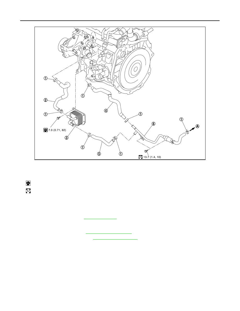
JPBIA4445GB

1.

Clamp

2.

Water hose

3.

Oil cooler

4.

Water hose

5.

Water hose

6.

Heater thermostat

A.

To CVT oil warmer

 : N·m (kg-m, in-lb)

 : N·m (kg-m, ft-lb)

OIL COOLER

LU-15

< REMOVAL AND INSTALLATION >

[MR FOR NISMO RS MODELS]

C

D

E

F

G

H

I

J

K

L

M

A

LU

N

P

O

INSPECTION AFTER INSTALLATION

1. Check the engine oil level and the engine coolant level and add engine oil and engine coolant. Refer to

LU-9, "Inspection"

 and 

CO-10, "Inspection"

.

2. Start the engine, and check that there is no leakage of engine oil or engine coolant.
3. Stop the engine and wait for 10 minutes.
4. Check the engine oil level and the engine coolant level again. Refer to 

LU-9, "Inspection"

 and 

CO-10,

"Inspection"

.

LU-16

< UNIT DISASSEMBLY AND ASSEMBLY >

[MR FOR NISMO RS MODELS]

OIL PUMP

UNIT DISASSEMBLY AND ASSEMBLY

OIL PUMP

Exploded View

INFOID:0000000012197480

1.

O-ring

2.

Oil pan (upper)

3.

Oil level gauge guide

4.

O-ring

5.

Oil level gauge

6.

Oil pump drive chain

7.

Crankshaft sprocket

8.

Oil pump sprocket

9.

Oil pump chain tensioner

10. Oil pump

11. Drain plug

12. Drain plug washer

13. Oil pan (lower)

14. Oil filter

15. Connector bolt

16. Clamp

17. Oil cooler hose

18. Oil cooler

19. Crankshaft position sensor

20. Gasket

21. Oil pan bolt

22. Rear oil seal

A.

Comply with the assembly proce-
dure when tightening. Refer to 

LU-12

B.

To thermostat housing

C.

To thermostat housing (M/T models)
To CVT oil warmer (CVT models)

D.

Oil pan side

 : N·m (kg-m, ft-lb)

 : N·m (kg-m, in-lb)

 : Always replace after every disassembly.

JPBIA4875GB

OIL PUMP

LU-17

< UNIT DISASSEMBLY AND ASSEMBLY >

[MR FOR NISMO RS MODELS]

C

D

E

F

G

H

I

J

K

L

M

A

LU

N

P

O

Removal and Installation

INFOID:0000000012197481

REMOVAL

1. Remove engine assembly. Refer to 

EM-62, "2WD : Exploded View"

 (2WD) 

EM-68, "AWD : Exploded

View"

 (AWD).

2. Remove oil pan (lower). Refer to 

EM-47, "Removal and Installation"

.

3. Remove front cover, and other related parts. Refer to 

EM-76, "Exploded View"

.

4. Remove oil pump sprocket with the following procedure: 

• Add matching mark if necessary for easier installation.

a. Push oil pump drive chain tensioner (1) in the direction show in

the figure.

b. Insert a stopper pin (A) into the body hole (B).
c. Remove oil pump chain tensioner.

• When the holes on lever and tensioner body cannot be

aligned, align these holes by slightly moving the oil pump

chain tensioner slack guide.

d. Hold the WAF part of oil pump shaft [WAF: 10 mm (0.39 in)] (A),

and then loosen the oil pump sprocket bolt and remove it.

CAUTION:

• Secure the oil pump shaft with the WAF part.

• Never loosen the oil pump sprocket bolt by tightening the

oil pump drive chain.

e. Remove oil pump sprocket.

5. Remove oil pump.

 : Should be lubricated with oil.

 : Sealing point

 : Indicates that the parts is connected at points with same symbols in actual vehicle.

JPBIA4397ZZ

1

: Oil pan (upper)

: Engine front

JPBIA4398ZZ


Content   ..  969  970  971  972   ..