Nissan Juke F15. Manual - part 913
IP-16
< REMOVAL AND INSTALLATION >
INSTRUMENT PANEL ASSEMBLY
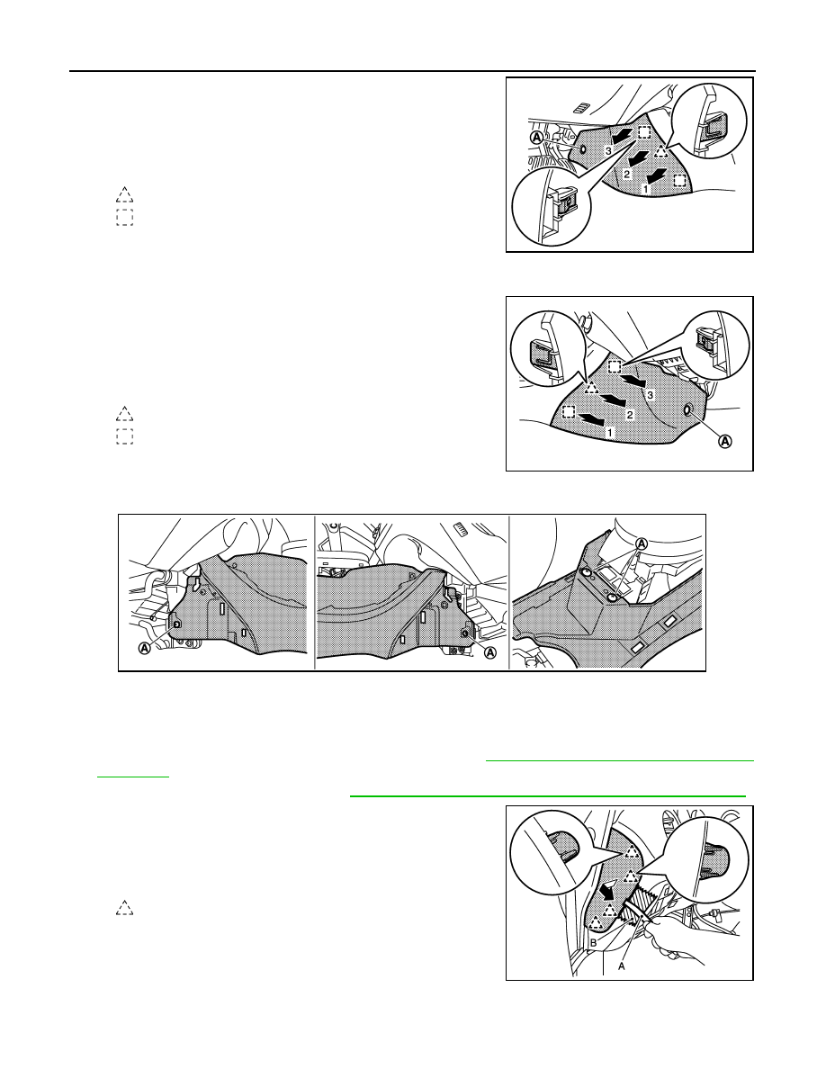
2. Remove fixing clip (A).
3. Pull the instrument lower cover LH crosswise, and disen-
gage the pawl and metal clips.
CAUTION:
Remove pawl and metal clips slowly so that they are not
damaged.
6. Remove instrument lower cover RH.
1. Put front seat assembly RH to rearmost position.
2. Remove fixing clip (A).
3. Pull the instrument lower cover RH crosswise, and disen-
gage the pawl and metal clips.
CAUTION:
Remove pawl and metal clips slowly so that they are not
damaged.
7. Remove center console assembly.
1. Remove center console fixing screws (A).
2. Remove seat heated switch harness clip (with seat heated switch).
3. Lift up center console assembly back side.
CAUTION:
Be careful not for damaging parts in surrounding area.
8. Release front pillar portion of front body side welt LH. Refer to
INT-21, "BODY SIDE WELT : Removal and
.
9. Remove front pillar garnish LH. Refer to
INT-18, "FRONT PILLAR GARNISH : Removal and Installation"
.
10. Remove instrument side finisher LH.
1. Insert remover tool (A) between instrument side finisher LH
and instrument panel assembly to disengage the pawls as
shown in the figure.
2. Pull back instrument side finisher LH.
CAUTION:
Apply protective tape (B) on the part to protect it from dam-
age.
11. Remove instrument lower panel LH.
: Pawl
: Metal clip
JMJIA4551ZZ
: Pawl
: Metal clip
JMJIA4552ZZ
JMJIA4553ZZ
: Pawl
JMJIA4554ZZ