Nissan Juke F15. Manual - part 841


  Index      Nissan     Nissan Juke F15 (2015 year) - Service and Repair Manual


Search            


Content   ..  839  840  841  842   ..


Nissan Juke F15. Manual - part 841


A/C UNIT ASSEMBLY

HA-47

< REMOVAL AND INSTALLATION >

C

D

E

F

G

H

J

K

L

M

A

B

HA

N

O

P

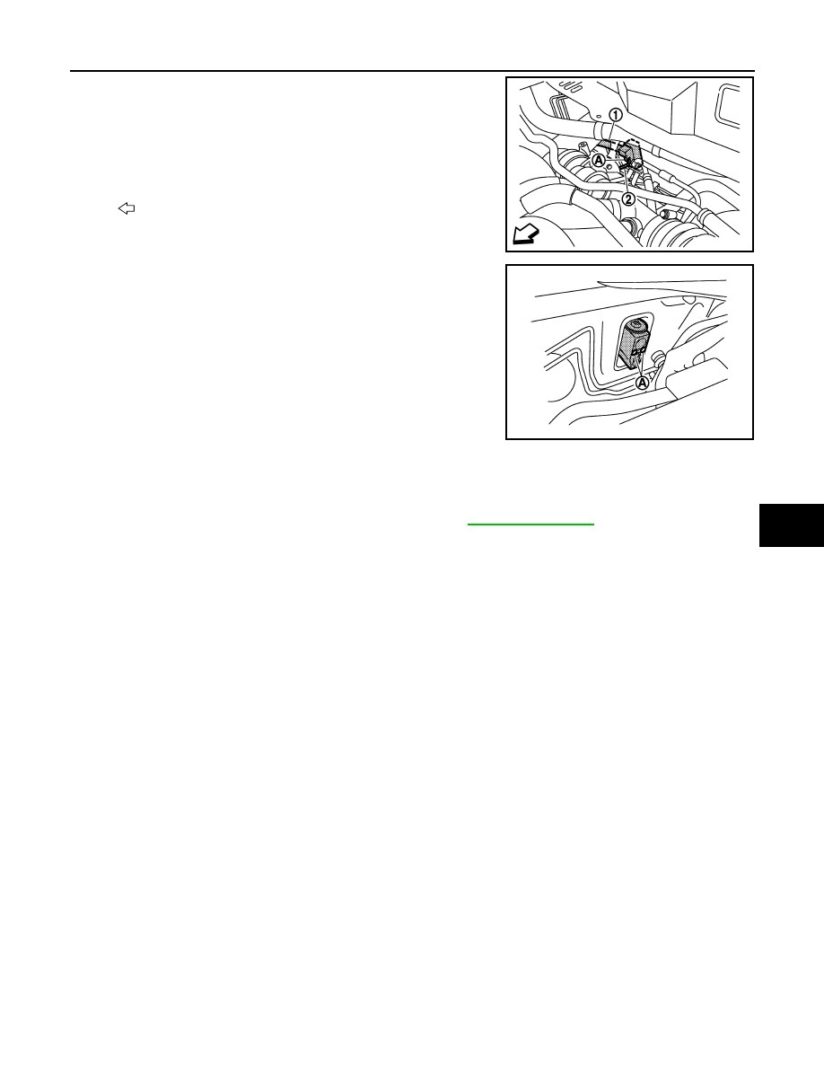
4. Remove mounting bolt (A), and then disconnect low-pressure

flexible hose (1) and high-pressure pipe (2) from expansion

valve.

CAUTION:

Cap or wrap the joint of the A/C piping and expansion valve

with suitable material such as vinyl tape to avoid the entry

of air.

5. Remove mounting bolts (A), and then remove expansion valve.

INSTALLATION

Note the following items, and then install in the reverse order of removal.

CAUTION:

• Replace O-rings with new ones. Then apply compressor oil to them when installing.

• Check for leakages when recharging refrigerant. Refer to 

HA-17, "Leak Test"

.

: Vehicle front

JMIIA0974ZZ

JMIIA0883ZZ

HA-48

< SERVICE DATA AND SPECIFICATIONS (SDS) 

SERVICE DATA AND SPECIFICATIONS (SDS)

SERVICE DATA AND SPECIFICATIONS (SDS)

SERVICE DATA AND SPECIFICATIONS (SDS)

Compressor

INFOID:0000000012197140

Lubricant

INFOID:0000000012197141

Refrigerant

INFOID:0000000012197142

Engine Idling Speed

INFOID:0000000012197143

Refer to 

EC-591, "Idle Speed"

 (MR for NISMO RS models) or 

EC-1258, "Idle Speed"

 (MR except for NISMO

RS models).

Belt Tension

INFOID:0000000012197144

Refer to 

EM-21, "Inspection"

 (MR for NISMO RS models) or 

EM-186, "Inspection"

 (MR except for NISMO RS

models).

Model

CALSONIC KANSEI make

CR-08b

Type

Vane rotary

Displacement
cm

3

 (cu in)/rev

Maximum

83 (5.1)

Direction of rotation

Clockwise (viewed from clutch)

Drive belt

Poly V

Disc to pulley clearance
mm (in)

Standard

0.3 – 0.6 (0.012 – 0.024)

Name

A/C System Oil Type R (DH-PR)

Capacity
m  (US fl oz, Imp fl oz)

Total in system

120 (4.1, 4.2)

Compressor (service part) charging 
amount

120 (4.1, 4.2)

Type

HFC-134a (R-134a)

Capacity
kg (lb)

0.40 (0.9)

HAC-1

VENTILATION, HEATER & AIR CONDITIONER

C

D

E

F

G

H

J

K

L

M

SECTION 

HAC

A

B

HAC

N

O

P

CONTENTS

HEATER & AIR CONDITIONING CONTROL SYSTEM

AUTOMATIC AIR CONDITIONING

PRECAUTION ...............................................

5

PRECAUTIONS ...................................................

5

Precaution for Supplemental Restraint System 
(SRS) "AIR BAG" and "SEAT BELT PRE-TEN-
SIONER" .................................................................
..

5

Precautions for Removing Battery Terminal  .............

5

SYSTEM DESCRIPTION  ..............................

7

COMPONENT PARTS  ........................................

7

Component Parts Location ........................................

7

Component Description .............................................

8

A/C UNIT ASSEMBLY .................................................

8

A/C UNIT ASSEMBLY : Aspirator .............................

8

A/C UNIT ASSEMBLY : Intake Sensor  .....................

8

A/C UNIT ASSEMBLY : Air Mix Door Motor  .............

8

A/C UNIT ASSEMBLY : Mode Door Motor  ...............

9

A/C UNIT ASSEMBLY : Intake Door Motor ...............

9

A/C UNIT ASSEMBLY : Blower Motor  ......................

9

A/C UNIT ASSEMBLY : Power Transistor ................

9

Multi Display Unit  ....................................................

10

A/C Auto Amp.  ........................................................

10

BCM ........................................................................

10

ECM ........................................................................

10

IPDM E/R  ................................................................

10

Ambient Sensor .......................................................

10

In-vehicle Sensor  ....................................................

10

Sunload Sensor .......................................................

10

Refrigerant Pressure Sensor ...................................

10

Magnet Clutch  .........................................................

11

SYSTEM .............................................................

12

System Diagram ......................................................

12

System Description  .................................................

12

Temperature Control  ...............................................

13

Air Outlet Control .....................................................

14

Air Flow Control .......................................................

14

Air Inlet Control  .......................................................

15

Compressor Control  ................................................

15

Door Control  ............................................................

16

ECO Mode Control  ..................................................

19

Fail-safe ...................................................................

19

OPERATION .....................................................

21

Switch Name and Function ......................................

21

DIAGNOSIS SYSTEM (A/C AUTO AMP.)  ........

24

Description ...............................................................

24

CONSULT Function .................................................

24

DIAGNOSIS SYSTEM (BCM)  ...........................

27

COMMON ITEM  .........................................................

27

COMMON ITEM : CONSULT Function (BCM - 
COMMON ITEM)  .....................................................

27

AIR CONDITIONER  ...................................................

28

AIR CONDITIONER : CONSULT Function (BCM - 
AIR CONDITIONER) (Automatic A/C) .....................

28

ECU DIAGNOSIS INFORMATION ..............

30

A/C AUTO AMP.  ...............................................

30

Reference Value ......................................................

30

Fail-safe ...................................................................

33

DTC Index  ...............................................................

33

MULTI DISPLAY UNIT, BCM, ECM, IPDM E/R 

...

34

List of ECU Reference .............................................

34

WIRING DIAGRAM ......................................

35

AUTOMATIC AIR CONDITIONING SYSTEM ...

35

Wiring Diagram ........................................................

35

BASIC INSPECTION  ...................................

45

DIAGNOSIS AND REPAIR WORK FLOW  .......

45

Work Flow ................................................................

45

HAC-2

OPERATION INSPECTION ...............................

48

Work Procedure ......................................................

48

SYSTEM SETTING ............................................

50

Temperature Setting Trimmer ................................

50

Inlet Port Memory Function (REC)  .........................

50

Inlet Port Memory Function (FRE) ..........................

51

Foot Position Setting Trimmer  ................................

51

DOOR MOTOR STARTING POSITION RE-
SET ....................................................................

52

Description ..............................................................

52

Work Procedure ......................................................

52

DTC/CIRCUIT DIAGNOSIS .........................

53

U1000 CAN COMM CIRCUIT  ............................

53

Description ..............................................................

53

DTC Logic ...............................................................

53

Diagnosis Procedure  ..............................................

53

U1010 CONTROL UNIT (CAN)  .........................

54

Description ..............................................................

54

DTC Logic ...............................................................

54

Diagnosis Procedure  ..............................................

54

B2578, B2579 IN-VEHICLE SENSOR ...............

55

DTC Logic ...............................................................

55

Diagnosis Procedure  ..............................................

55

Component Inspection ............................................

56

B257B, B257C AMBIENT SENSOR  .................

58

DTC Logic ...............................................................

58

Diagnosis Procedure  ..............................................

58

Component Inspection ............................................

59

B2581, B2582 INTAKE SENSOR ......................

61

DTC Logic ...............................................................

61

Diagnosis Procedure  ..............................................

61

Component Inspection ............................................

62

B2630, B2631 SUNLOAD SENSOR  .................

64

DTC Logic ...............................................................

64

Diagnosis Procedure  ..............................................

64

Component Inspection ............................................

65

B27A0, B27A1 INTAKE DOOR MOTOR  ..........

67

DTC Logic ...............................................................

67

Diagnosis Procedure  ..............................................

67

Component Inspection (PBR) .................................

69

Component Inspection (Motor)  ...............................

69

B27A2, B27A3, B27A4, B27A5 AIR MIX 
DOOR MOTOR  ..................................................

71

DTC Logic ...............................................................

71

Diagnosis Procedure  ..............................................

71

Component Inspection ............................................

72

B27A6, B27A7, B27A8, B27A9 MODE DOOR 
MOTOR ..............................................................

73

DTC Logic ...............................................................

73

Diagnosis Procedure ...............................................

73

Component Inspection  ............................................

74

POWER SUPPLY AND GROUND CIRCUIT .....

75

A/C AUTO AMP. ........................................................

75

A/C AUTO AMP. : Diagnosis Procedure .................

75

A/C ON SIGNAL  ................................................

77

Component Function Check  ...................................

77

Diagnosis Procedure ...............................................

77

BLOWER FAN ON SIGNAL ..............................

79

Component Function Check  ...................................

79

Diagnosis Procedure ...............................................

79

BLOWER MOTOR .............................................

81

Diagnosis Procedure ...............................................

81

Component Inspection (Blower Motor)  ...................

83

Component Inspection (Blower Relay)  ...................

84

MAGNET CLUTCH ............................................

85

Component Function Check  ...................................

85

Diagnosis Procedure ...............................................

85

SYMPTOM DIAGNOSIS  ............................

86

AUTOMATIC AIR CONDITIONER SYSTEM  ....

86

Symptom Table .......................................................

86

INSUFFICIENT COOLING .................................

88

Description ..............................................................

88

Diagnosis Procedure ...............................................

88

INSUFFICIENT HEATING  .................................

90

Description ..............................................................

90

Diagnosis Procedure ...............................................

90

COMPRESSOR DOES NOT OPERATE  ...........

91

Description ..............................................................

91

Diagnosis Procedure ...............................................

91

REMOVAL AND INSTALLATION ..............

92

CONTROLLER ..................................................

92

Removal and Installation .........................................

92

A/C AUTO AMP. ................................................

93

Removal and Installation .........................................

93

AMBIENT SENSOR ...........................................

94

Removal and Installation .........................................

94

IN-VEHICLE SENSOR .......................................

95

Removal and Installation .........................................

95

SUNLOAD SENSOR  .........................................

96

Removal and Installation .........................................

96

INTAKE SENSOR ..............................................

97

Exploded View  ........................................................

97

Removal and Installation .........................................

97


Content   ..  839  840  841  842   ..