Nissan Juke F15. Manual - part 797
FL-18
< REMOVAL AND INSTALLATION >
[MR16DDT ]
FUEL TANK
FUEL TANK
2WD
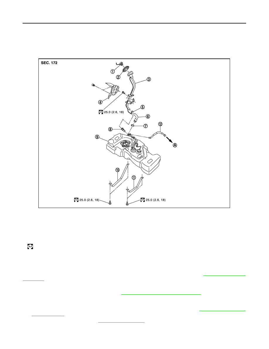
2WD : Exploded View
INFOID:0000000012197591
2WD : Removal and Installation
INFOID:0000000012197592
WARNING:
Be sure to read “General Precautions” when working on the fuel system. Refer to
.
REMOVAL
• Drain fuel from fuel tank if necessary. Refer to
FL-7, "2WD : Removal and Installation"
.
• Perform work on level place.
1. Perform steps 2 to 7 of “REMOVAL” in “FUEL LEVEL SENSOR UNIT, FUEL FILTER AND FUEL PUMP
ASSEMBLY” on fuel level sensor unit, fuel filter and fuel pump assembly. Refer to
2. Remove center muffler. Refer to
3. Remove insulator on vehicle side located above center and main mufflers.
1.
Fuel filler cap
2.
Grommet
3.
Fuel filler tube
4.
Cover
5.
Clamp
6.
Fuel filler hose
7.
Clamp
8.
EVAP canister protector
9.
Fuel tank
10. Fuel tank mounting band (RH)
11.
Fuel tank mounting band (LH)
12. Vent tube
A.
To EVAP canister
: N·m (kg-m, ft-lb)
JPBIA2894GB