Nissan Juke F15. Manual - part 796


  Index      Nissan     Nissan Juke F15 (2015 year) - Service and Repair Manual


Search            


Content   ..  794  795  796  797   ..


Nissan Juke F15. Manual - part 796


FL-14

< REMOVAL AND INSTALLATION >

[MR16DDT ]

FUEL LEVEL SENSOR UNIT, FUEL FILTER AND FUEL PUMP ASSEMBLY

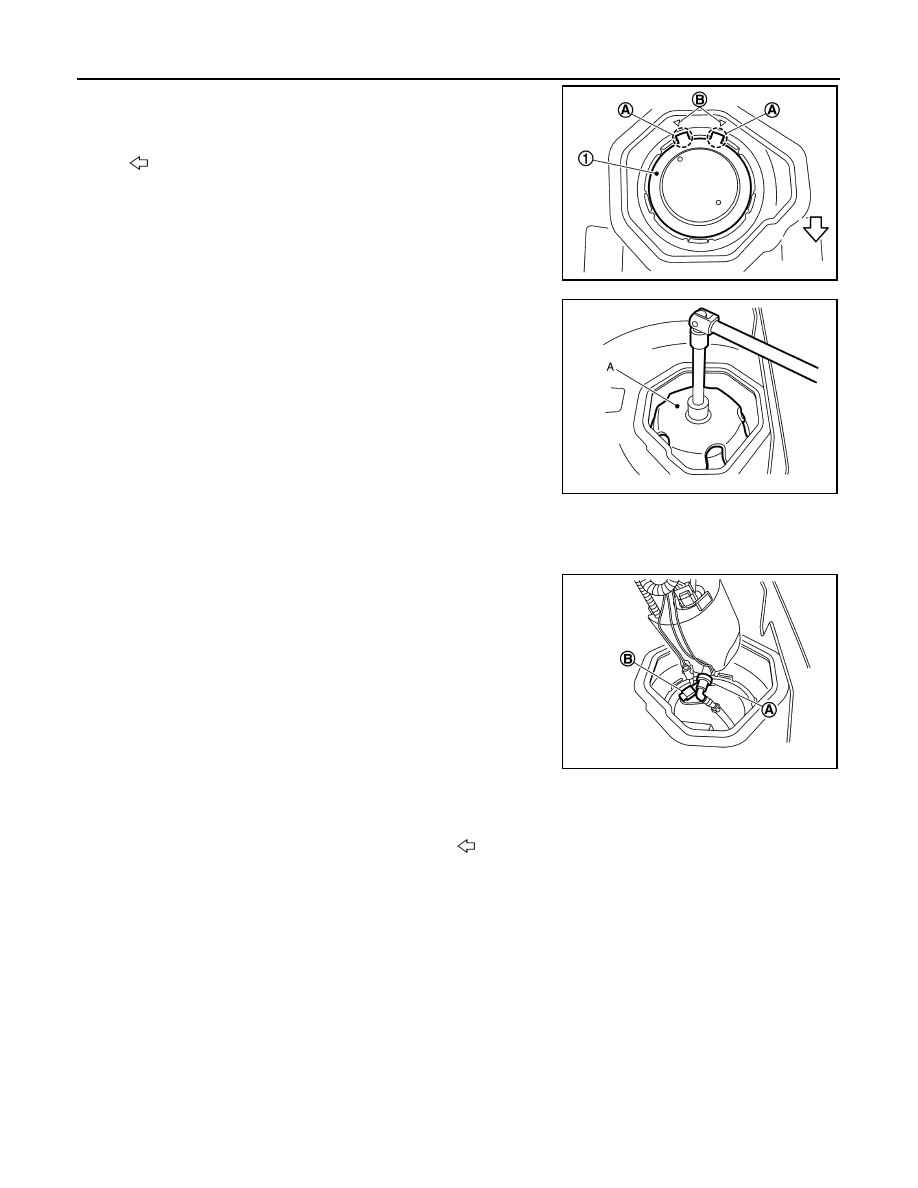
3. Install sub fuel level sensor assembly (1) with its matching mark

(A) aligned with fuel tank matching mark (B) as shown in the fig-

ure.

NOTE:

• Figure shows fuel level sensor unit, fuel filter and fuel pump

assembly side of fuel tank.

• For sub fuel level sensor assembly matching mark is located

on the fuel tank of the vehicle rear side.

4. Install lock ring for sub fuel level sensor assembly with lock ling

wrench (A) by turning clockwise.

Fuel Level Sensor Unit, Fuel Filter and Fuel Pump Assembly

1. Temporarily install the O-ring to the fuel level sensor unit, fuel filter and fuel pump assembly.
2. Connect the fuel tube as per the following steps.

• Insert the quick connector (A) straight to the fuel level sensor

unit, fuel filter and fuel pump assembly.

• Judge a good fit from connecting sound and tactile feedback.

• Pull the fuel tube by hand to check a secure fit.

3. Connect harness connector (B).

4. Insert the fuel level sensor unit, fuel filter and fuel pump assembly to the fuel tank. 

CAUTION:

• Never bend float arm during installation. 
• To install, fuel tube (1) must run to the front (

) of the vehicle to avoid the interference with the

float arm (2), as shown in the figure.

: Vehicle front

JPBIA4468ZZ

Tool number (A)

: KV991J0090 (J-46214) (shown)
: KV101207S0 ( — )

JPBIA4463ZZ

JPBIA4465ZZ

FUEL LEVEL SENSOR UNIT, FUEL FILTER AND FUEL PUMP ASSEMBLY

FL-15

< REMOVAL AND INSTALLATION >

[MR16DDT ]

C

D

E

F

G

H

I

J

K

L

M

A

FL

N

P

O

• Through the clearance of the mounting part of the fuel level sensor unit and the fuel filter and

fuel pump assembly, visually check that the fuel tube is placed on the vehicle front side of them.

5. Install fuel level sensor unit, fuel filter and fuel pump assembly

(1) with its matching mark (A) aligned with fuel tank matching

mark (B) as shown in the figure.

6. Install lock ring for sub fuel level sensor assembly with lock ling

wrench (A) by turning clockwise.

7. Connect quick connector of fuel feed tube as per following procedures.
a. Check the connection for damage or any foreign materials.
b. Align the connector with the tube, then insert the connector straight into the tube until a “click” sound is

heard.

c. After connecting, check that the connection is secured with following procedures.

• Visually confirm that the two tabs are connected to the connector. 

: Vehicle front

JPBIA4467ZZ

JPBIA4469ZZ

Tool number (A)

: KV991J0090 (J-46214) (shown)
: KV101207S0 ( — )

JPBIA4463ZZ

FL-16

< REMOVAL AND INSTALLATION >

[MR16DDT ]

FUEL LEVEL SENSOR UNIT, FUEL FILTER AND FUEL PUMP ASSEMBLY

• Pull (A) the tube and the connector to check that they are

securely connected.

8. Connect harness connector.

Inspection Hole Cover

• Before installing inspection hole cover, check that the connecting part has no fuel leakage. Refer to 

FL-10,

"2WD : Inspection"

.

1. Install inspection hole covers with the front mark (arrow) facing front of vehicle. 

AWD : Disassembly and Assembly

INFOID:0000000012197589

DISASSEMBLY

CAUTION:

Sub fuel level sensor unit cannot be disassembled and should be replaced as a unit.
1. Disconnect harness connector (A).

2. Press (A) with a flat-blade screwdriver or an equivalent to

release lock and push out the fuel level senor unit (1).

3. To remove the fuel level sensor unit (1), side it in the direction

(

) of the arrow with the lock release.

ASSEMBLY

JPBIA0140ZZ

JPBIA4471ZZ

JPBIA4472ZZ

JPBIA4473ZZ

FUEL LEVEL SENSOR UNIT, FUEL FILTER AND FUEL PUMP ASSEMBLY

FL-17

< REMOVAL AND INSTALLATION >

[MR16DDT ]

C

D

E

F

G

H

I

J

K

L

M

A

FL

N

P

O

1. Check for damage of fuel level sensor unit installation position on the side of fuel filter and pump assem-

bly.

2. Slide fuel level sensor unit until it aligns to installation groove, then insert it until stops.

• After inserting, apply force in reverse direction (removal direction) to ensure it cannot be pulled out.

3. Connect harness connector.

AWD : Inspection

INFOID:0000000012197590

INSPECTION AFTER INSTALLATION

Use the following procedure to check for fuel leakage.
1. Turn ignition switch “ON” (with engine stopped), then check connections for leakage by applying fuel pres-

sure to fuel piping.

2. Start engine and let it idle and check there are no fuel leakage at the fuel system connections.


Content   ..  794  795  796  797   ..