Nissan Juke F15. Manual - part 790
FRONT DRIVE SHAFT
FAX-99
< REMOVAL AND INSTALLATION >
[TYPE 2]
C
E
F
G
H
I
J
K
L
M
A
B
FAX
N
O
P
7. Patch wheel hub lock nut with a piece of wood. Hammer the
wood to disengage wheel hub assembly from drive shaft.
NOTE:
Use suitable puller, if wheel hub assembly and drive shaft can-
not be separated even after performing the above procedure.
8. Remove wheel hub lock nut.
9. Remove strut assembly from steering knuckle. Refer to
FSU-9, "Removal and Installation"
.
10. Remove drive shaft from wheel hub assembly.
CAUTION:
• Never place drive shaft joint at an extreme angle. Also be careful not to overextend slide joint.
• Never allow drive shaft to hang down without support for joint sub-assembly, shaft and the other
parts.
11. Remove bearing housing bolts.
12. Remove drive shaft assembly from transfer assembly.
CAUTION:
Never place drive shaft joint at an extreme angle when removing drive shaft. Also be careful not to
overextend slide joint.
INSTALLATION
Note the following, and install in the reverse order of removal.
Left Side
• Always replace differential side oil seal with new one when installing drive shaft. Refer to
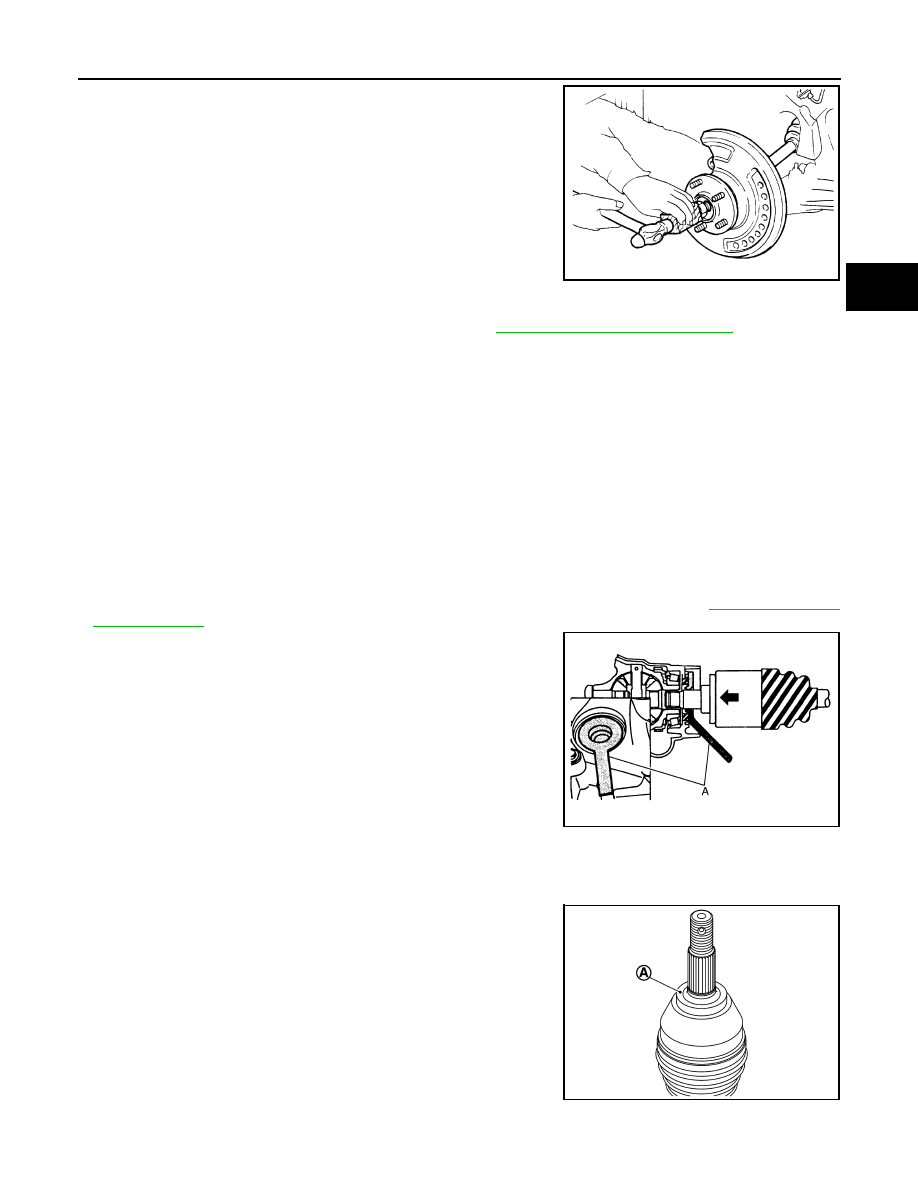
• Place the protector (A) [SST:KV38107900 ( — )] onto tranaxle
assembly to prevent damage to the oil seal while inserting drive
shaft. Slide drive shaft sliding joint and tap with a hammer to install
securely.
CAUTION:
• Check that circular clip is completely engaged.
• Never reuse circular clip.
• Never reuse differential side oil seal.
• Clean the matching surface of wheel hub lock nut and wheel hub assembly.
CAUTION:
Never apply lubricating oil to these matching surface.
• Clean the matching surface of drive shaft and wheel hub assembly.
And then apply paste [service parts (440037S000)] to surface (A)
of joint sub-assembly of drive shaft.
CAUTION:
Apply paste to cover entire flat surface of joint sub-assembly
of drive shaft.
• Use the following torque range for tightening the wheel hub lock nut.
JPDIG0070ZZ
JPDIF0023ZZ
Amount paste
: 1.0 – 3.0 g (0.04 – 0.10 oz)
JSDIA2844ZZ