Nissan Juke F15. Manual - part 791
FRONT DRIVE SHAFT
FAX-103
< REMOVAL AND INSTALLATION >
[TYPE 2]
C
E
F
G
H
I
J
K
L
M
A
B
FAX
N
O
P
6. Align both center axles of the shaft edge and joint sub-assembly. Then assemble shaft with joint sub-
assembly holding circular clip.
7. Install joint sub-assembly to shaft using plastic hammer.
CAUTION:
• Check circular clip is properly positioned on groove of the
joint sub-assembly.
• Confirm that joint sub-assembly is correctly engaged
while rotating drive shaft.
8. Apply the specified amount of grease into the boot inside from large diameter side of boot.
9. Install the boot securely into grooves (indicated by “*” marks)
shown in the figure.
CAUTION:
If grease adheres to the boot mounting surface (indicated
by “*” marks) on the shaft or joint sub-assembly, boot may
be removed. Remove all grease from the boot mounting
surface.
10. To prevent the deformation of the boot, adjust the boot installation length (L) to the specified value shown
below by inserting the suitable tool into inside of the boot from the large diameter side of the boot and dis-
charging the inside air.
CAUTION:
• If the boot installation length exceeds the standard, it may cause breakage of the boot.
• Be careful not to touch the inside of the boot with a tip of tool.
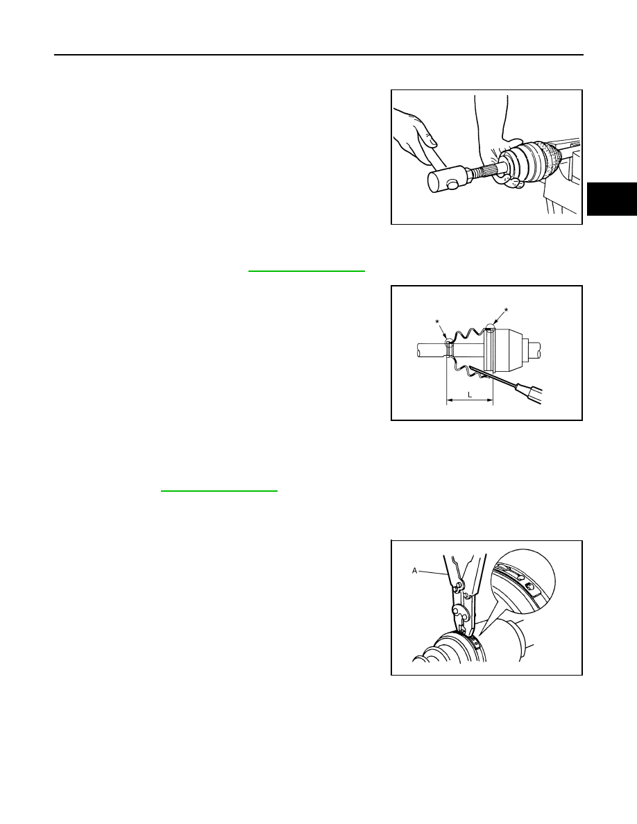
11. Secure the large and small ends of the boot with boot bands
using the boot band crimping tool (A) [SST:KV40107300 ( —
)].
CAUTION:
• Never reuse boot band.
RAC0049D
Grease amount
: Refer to
.
JSDIA2261ZZ
L : Refer to
.
JPDIF0012ZZ