Nissan Juke F15. Manual - part 776


  Index      Nissan     Nissan Juke F15 (2015 year) - Service and Repair Manual


Search            


Content   ..  774  775  776  777   ..


Nissan Juke F15. Manual - part 776


FRONT DRIVE SHAFT

FAX-43

< REMOVAL AND INSTALLATION >

[TYPE 1]

C

E

F

G

H

I

J

K

L

M

A

B

FAX

N

O

P

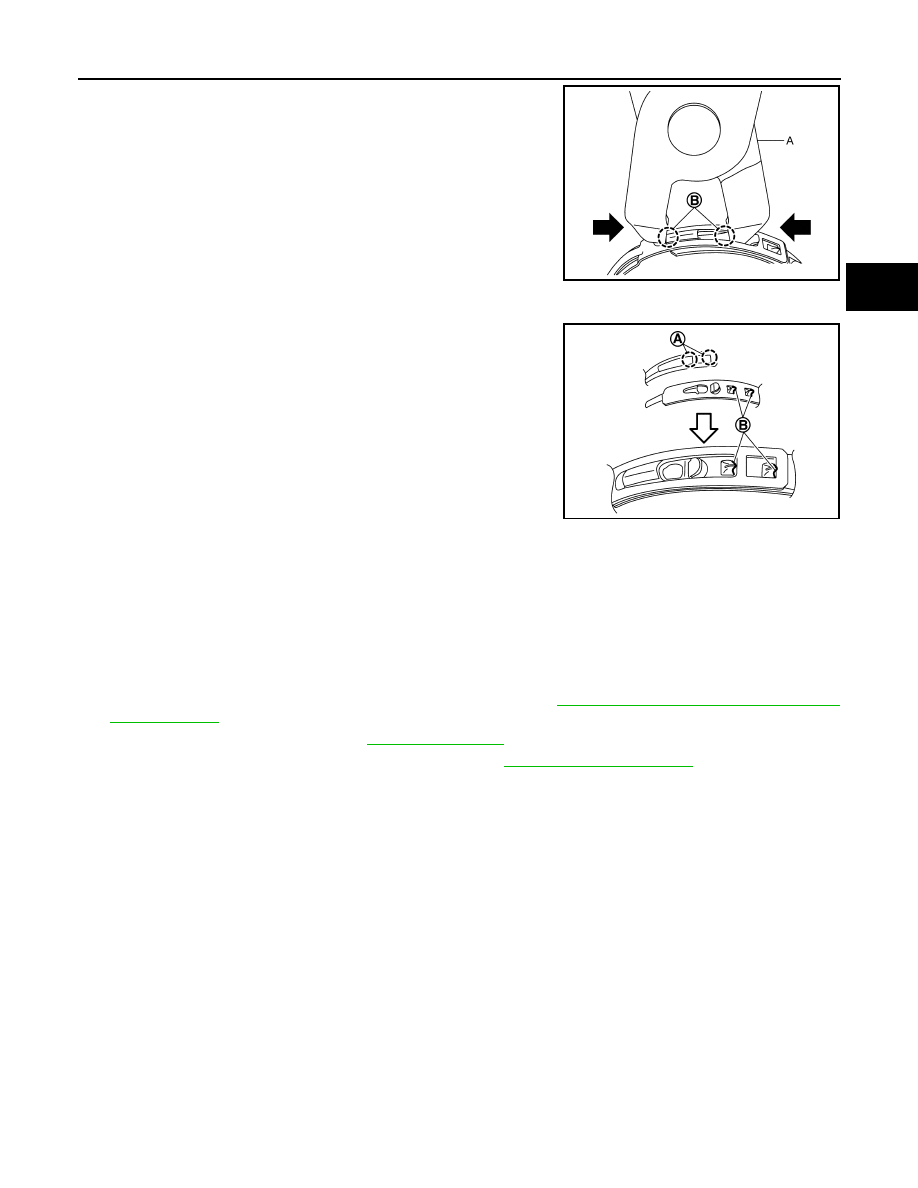
b. Tighten boot band protrusions (B) with boot band crimping tool

(A) [SST:KV40107310 ( — )] in the direction shown by

arrows.

CAUTION:

Securely install boot band (A) to boot band pawl (B).

15. Check that displacement does not occur when boot is rotated with the housing assembly fixed.

CAUTION:

• If displacement occurs, reinstall band.

• Never reuse boot band.

2WD : Inspection

INFOID:0000000012201536

INSPECTION AFTER INSTALLATION

1. Check wheel sensor harness for proper connection. Refer to 

BRC-147, "FRONT WHEEL SENSOR :

Exploded View"

.

2. Check the wheel alignment. Refer to 

FSU-7, "Inspection"

.

3. Adjust neutral position of steering angle sensor. Refer to 

BRC-63, "Work Procedure"

.

AWD
AWD : Exploded View

INFOID:0000000012201537

LEFT SIDE

JSDIA6966ZZ

JSDIA6968ZZ

FAX-44

< REMOVAL AND INSTALLATION >

[TYPE 1]

FRONT DRIVE SHAFT

RIGHT SIDE

1.

Circular clip

2.

Dust shield

3.

Housing assembly

4.

Boot band

5.

Boot

6.

Damper band

7.

Dynamic damper

8.

Circular clip

9.

Joint sub-assembly

: Wheel side

: Fill NISSAN Genuine grease or equivalent.

: Always replace after every disassembly.

JSDIA2093ZZ

1.

Joint sub-assembly

2.

Circular clip

3.

Boot band

4.

Boot

5.

Damper band

6.

Dynamic damper

7.

Housing assembly

: Wheel side

: Fill NISSAN Genuine grease or equivalent.

: Always replace after every disassembly.

: N·m (kg-m, ft-lb)

JSDIA2095GB

FRONT DRIVE SHAFT

FAX-45

< REMOVAL AND INSTALLATION >

[TYPE 1]

C

E

F

G

H

I

J

K

L

M

A

B

FAX

N

O

P

AWD : Removal and Installation

INFOID:0000000012201538

REMOVAL

Left Side

1. Remove tires with power tool. Refer to 

WT-39, "Removal and Installation"

.

2. Remove wheel sensor and sensor harness. Refer to 

BRC-147, "FRONT WHEEL SENSOR : Exploded

View"

.

3. Remove lock plate from strut assembly. Refer to 

BR-25, "FRONT : Removal and Installation"

.

4. Remove caliper assembly. Hang caliper assembly not to interfere with work. Refer to 

BR-55, "BRAKE

CALIPER ASSEMBLY : Removal and Installation"

.

CAUTION:

Never depress brake pedal while brake caliper is removed.

5. Remove disc rotor.

CAUTION:

• Put matching marks (A) on the wheel hub assembly and

the disc rotor before removing the disc rotor.

• Never drop disc rotor.

6. Remove cotter pin, and adjusting cap, and then loosen wheel hub lock nut with power tool.
7. Patch wheel hub lock nut with a piece of wood. Hammer the

wood to disengage wheel hub assembly from drive shaft.

NOTE:

Use suitable puller, if wheel hub assembly and drive shaft can-

not be separated even after performing the above procedure.

8. Remove wheel hub lock nut.
9. Remove strut assembly from steering knuckle. Refer to 

FSU-9, "Removal and Installation"

.

10. Remove draive shaft from wheel hub assembly.

CAUTION:

• Never place drive shaft joint at an extreme angle. Also be careful not to overextend slide joint.

• Never allow drive shaft to hang down without support for joint sub-assembly, shaft and the other

parts.

11. Use the drive shaft attachment (A) [SST:KV40107500 ( — )]

and a sliding hammer (B) (commercial service tool) while insert-

ing tip of the drive shaft attachment between shaft and transaxle

assembly, and then remove drive shaft from transaxle assembly.

CAUTION:

• Never place drive shaft joint at an extreme angle when

removing drive shaft. Also be careful not to overextend

slide joint.

• Confirm that the circular clip is attached to the drive shaft.

JPDIG0066ZZ

JPDIG0070ZZ

JPDIF0004ZZ

FAX-46

< REMOVAL AND INSTALLATION >

[TYPE 1]

FRONT DRIVE SHAFT

Right Side

1. Remove tires with power tool. Refer to 

WT-39, "Removal and Installation"

.

2. Remove wheel sensor and sensor harness. Refer to 

BRC-147, "FRONT WHEEL SENSOR : Exploded

View"

.

3. Remove lock plate from strut assembly. Refer to 

BR-25, "FRONT : Removal and Installation"

.

4. Remove caliper assembly. Hang caliper assembly not to interfere with work. Refer to 

BR-55, "BRAKE

CALIPER ASSEMBLY : Removal and Installation"

.

CAUTION:

Never depress brake pedal while brake caliper is removed.

5. Remove disc rotor.

CAUTION:

• Put matching marks (A) on the wheel hub assembly and

the disc rotor before removing the disc rotor.

• Never drop disc rotor.

6. Remove cotter pin, and adjusting cap, and then loosen wheel hub lock nut with power tool.
7. Patch wheel hub lock nut with a piece of wood. Hammer the

wood to disengage wheel hub assembly from drive shaft.

NOTE:

Use suitable puller, if wheel hub assembly and drive shaft can-

not be separated even after performing the above procedure.

8. Remove wheel hub lock nut.
9. Remove strut assembly from steering knuckle. Refer to 

FSU-9, "Removal and Installation"

.

10. Remove drive shaft from wheel hub assembly.

CAUTION:

• Never place drive shaft joint at an extreme angle. Also be careful not to overextend slide joint.

• Never allow drive shaft to hang down without support for joint sub-assembly, shaft and the other

parts.

11. Remove bearing housing bolts.
12. Remove drive shaft assembly from transfer assembly.

CAUTION:

Never place drive shaft joint at an extreme angle when removing drive shaft. Also be careful not to

overextend slide joint.

INSTALLATION

Note the following, and install in the reverse order of removal.

Left Side

• Always replace differential side oil seal with new one when installing drive shaft. Refer to 

TM-340, "Removal

and Installation"

.

JPDIG0066ZZ

JPDIG0070ZZ


Content   ..  774  775  776  777   ..