Nissan Juke F15. Manual - part 774


  Index      Nissan     Nissan Juke F15 (2015 year) - Service and Repair Manual


Search            


Content   ..  772  773  774  775   ..


Nissan Juke F15. Manual - part 774


FRONT DRIVE SHAFT

FAX-35

< REMOVAL AND INSTALLATION >

[TYPE 1]

C

E

F

G

H

I

J

K

L

M

A

B

FAX

N

O

P

c. Press out support bearing from housing.

d. Remove dust shield from housing.
10. Remove damper bands, then remove dynamic damper from shaft.

ASSEMBLY

Wheel Side

1. Clean the old grease on joint sub-assembly with paper waste.
2. Fill serration slot joint sub-assembly (1) with NISSAN genuine

grease or equivalent until the serration slot and ball groove

become full to the brim.

CAUTION:

After applying grease, use a paper waste to wipe off old

grease that has oozed out.

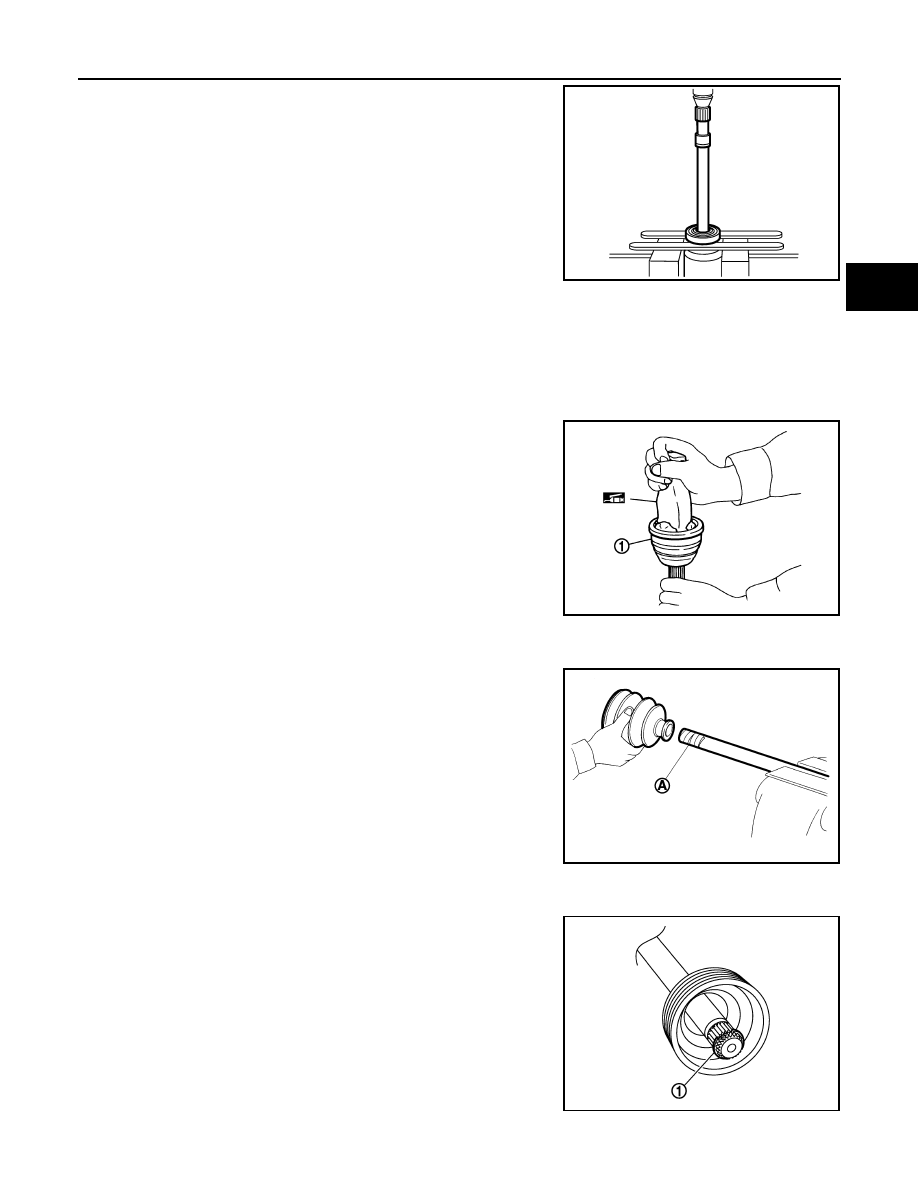
3. Install boot and boot bands to shaft.

CAUTION:

• Wrap serration on shaft with tape (A) to protect the boot

from damage.

• Never reuse boot and boot band.

4. Remove the tape wrapped around the serration on shaft.

5. Position the circular clip (1) on groove at the shaft edge.

CAUTION:

Never reuse circular clip.

NOTE:

Drive joint inserter is recommended when installing circular clip.

YAX004

JPDIF0008ZZ

JPDIF0009ZZ

JPDIF0305ZZ

FAX-36

< REMOVAL AND INSTALLATION >

[TYPE 1]

FRONT DRIVE SHAFT

6. Align both center axles of the shaft edge and joint sub-assembly. Then assemble shaft with joint sub-

assembly holding circular clip.

7. Install joint sub-assembly to shaft using plastic hammer.

CAUTION:

• Check circular clip is properly positioned on groove of the

joint sub-assembly.

• Confirm that joint sub-assembly is correctly engaged

while rotating drive shaft.

8. Apply the specified amount of grease into the boot inside from large diameter side of boot.

9. Install the boot securely into grooves (indicated by “*” marks)

shown in the figure.

CAUTION:

If grease adheres to the boot mounting surface (indicated

by “*” marks) on the shaft or joint sub-assembly, boot may

be removed. Remove all grease from the boot mounting

surface.

10. To prevent the deformation of the boot, adjust the boot installation length (L) to the specified value shown

below by inserting the suitable tool into inside of the boot from the large diameter side of the boot and dis-

charging the inside air.

CAUTION:

• If the boot installation length exceeds the standard, it may cause breakage of the boot.

• Be careful not to touch the inside of the boot with a tip of tool.

11. Secure the large and small ends of the boot with boot bands

using the boot band crimping tool (A) [SST:KV40107300 ( —

)].

CAUTION:

• Never reuse boot band.

RAC0049D

Grease amount

: Refer to 

FAX-57, "Drive Shaft"

.

JSDIA2261ZZ

L : Refer to 

FAX-57, "Drive Shaft"

.

JPDIF0012ZZ

FRONT DRIVE SHAFT

FAX-37

< REMOVAL AND INSTALLATION >

[TYPE 1]

C

E

F

G

H

I

J

K

L

M

A

B

FAX

N

O

P

• Secure boot band so that dimension (M) meets the speci-

fication as shown in the figure.

12. Check that displacement does not occur when boot is rotated with the joint sub-assembly and shaft fixed.

CAUTION:

• Reinstall them using boot bands when boot installation positions become incorrect.

• Never reuse boot band.

Transaxle Side (Left Drive Shaft)

1. Clean the old grease on housing with paper waste.
2. Install dust shield to housing assembly.

CAUTION:

Never reuse dust shield.

3. Install circular clip to housing assembly.

CAUTION:

Never reuse circular clip.

4. Install dynamic damper, follow the procedure described below. 
a. Install dynamic damper to shaft.

b. Secure dynamic damper with bands in the following specified

position (A) when installing.

CAUTION:

Never reuse boot bands.

c. Install boot bands securely as showin in the figure.

5. Install boot and boot bands to housing assembly.

CAUTION:

Dimension (M)

: 1.0 – 4.0 mm (0.039 – 0.157 in)

DSF0047D

A : 

Refer 

to 

FAX-57, "Drive Shaft"

.

JPDIF0178ZZ

PDIA1188J

FAX-38

< REMOVAL AND INSTALLATION >

[TYPE 1]

FRONT DRIVE SHAFT

• Wrap serration on housing assembly with tape (A) to pro-

tect the boot from damage.

• Never reuse boot and boot band.

6. Remove the tape wrapped around the serration on shaft.
7. To install the spider assembly (1), align it with the matching

marks (A) on the shaft (2) put during the removal, and direct the

serration mounting surface (B) to the shaft.

8. Secure spider assembly onto shaft with snap ring (1).

CAUTION:

Never reuse snap ring.

9. Apply the appropriate amount of grease to spider assembly and sliding surface.
10. Align matching marks put during the removal of housing assembly.
11. Install stopper ring.

CAUTION:

Never reuse stopper ring.

12. Apply NISSAN genuine grease (refer to parts catalog) to housing assembly.

13. Install the boot securely into grooves (indicated by “*” marks)

shown in the figure.

CAUTION:

If grease adheres to the boot mounting surface (indicated

by “*” marks) on the shaft or housing assembly, boot may

be removed. Remove all grease from the boot mounting

surface.

JPDIF0009ZZ

JPDIF0017ZZ

JPDIF0014ZZ

Grease amount

: Refer to 

FAX-57, "Drive Shaft"

.

JSDIA2063ZZ


Content   ..  772  773  774  775   ..