Nissan Juke F15. Manual - part 718


  Index      Nissan     Nissan Juke F15 (2015 year) - Service and Repair Manual


Search            


Content   ..  716  717  718  719   ..


Nissan Juke F15. Manual - part 718


EXL-92

< PERIODIC MAINTENANCE >

[XENON TYPE]

HEADLAMP AIMING ADJUSTMENT

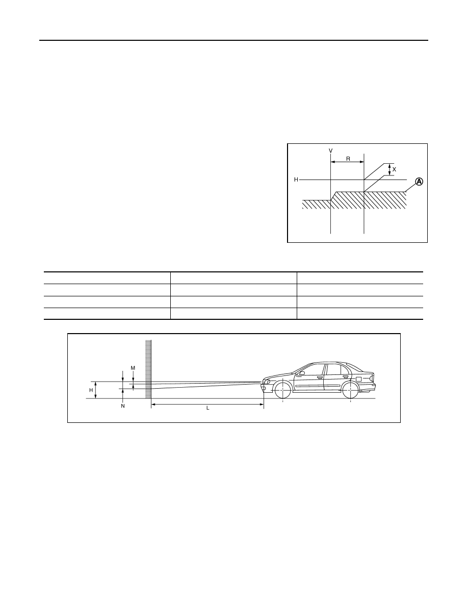
2. Face the vehicle with the screen. Maintain 10 m (32.8 ft) between the headlamp center and the screen.
3. Start the engine. Turn the headlamp (LO) ON.

CAUTION:

Never cover the lens surface with a tape etc. The lens is made of resin.

NOTE:

Shut off the headlamp light with the board to prevent from illuminating the adjustment screen.

4. Measure the distance (X) between the horizontal center line of headlamp (H) and the cutoff line (A) within

the light axis measurement range (R) from the vertical center line ahead of headlamp (V).

Low beam distribution on the screen 

5. Adjust the cutoff line height (X) with the aiming adjustment screw so as to enter in the adjustment range

(M–N) according to the horizontal center line of headlamp (H).

unit: mm (in)

Side view

Light axis measurement range (R)

: 350 

± 175 mm (13.78 ± 6.89 in)

JSLIA0005ZZ

Horizontal center line of headlamp (H)

Highest cutoff line height (M)

Lowest cutoff line height (N)

700 (27.56) or less

4 (0.16)

30 (1.18)

701(27.60) – 800 (31.50)

4 (0.16)

30 (1.18)

801 (31.54) or more

17 (0.67)

44 (1.73)

JSLIA0006ZZ

Distance between the headlamp center and the screen (L)

: 10 m (32.8 ft)

FRONT FOG LAMP AIMING ADJUSTMENT

EXL-93

< PERIODIC MAINTENANCE >

[XENON TYPE]

C

D

E

F

G

H

I

J

K

M

A

B

EXL

N

O

P

FRONT FOG LAMP AIMING ADJUSTMENT

Description

INFOID:0000000012201675

PREPARATION BEFORE ADJUSTING

NOTE:

• For details, refer to the regulations in your own country.

• Perform aiming if the vehicle front body has been repaired and/or the headlamp assembly has been

replaced.

Before performing aiming adjustment, check the following. 

• Adjust the tire pressure to the specification.

• Fill with fuel, engine coolant and each oil.

• Maintain the unloaded vehicle condition. (Remove luggage from the passenger compartment and the trunk

room.)

NOTE:

Do not remove the temporary tire, jack and on-vehicle tool. 

• Wipe out dirt on the headlamp.

CAUTION:

Never use organic solvent (thinner, gasoline etc.).

• Ride alone on the driver seat.

AIMING ADJUSTMENT SCREW

• Turn the aiming adjusting screw for adjustment.

• For the position and direction of the adjusting screw, refer to the

figure.

NOTE:

A screwdriver or hexagonal wrench [6 mm (0.24 in)] can be used

for adjustment.

Aiming Adjustment Procedure

INFOID:0000000012201676

1. Place the screen.

NOTE:

• Stop the vehicle facing the wall.

• Place the board on a plain road vertically.

2. Face the vehicle with the screen. Maintain 10 m (32.8 ft) between the front fog lamp center and the

screen.

3. Start the engine. Turn the front fog lamp ON.

CAUTION:

Never cover the lens surface with a tape etc. The lens is made of resin.

NOTE:

Shut off the headlamp light with the board to prevent from illuminating the adjustment screen.

4. Adjust the cutoff line height (A) with the aiming adjustment screw so that the distance (X) between the hor-

izontal center line of front fog lamp (H) and (A) becomes 150 mm (5.91 in).

A: UP
B: DOWN

JMLIA1249ZZ

EXL-94

< PERIODIC MAINTENANCE >

[XENON TYPE]

FRONT FOG LAMP AIMING ADJUSTMENT

Front fog lamp light distribution on the screen 

JPLIA0008ZZ

A

: Cutoff line

B

: High illuminance area

H

: Horizontal center line of front fog lamp

V

: Vertical center line of front fog lamp

X

: Cutoff line height

HEADLAMP

EXL-95

< REMOVAL AND INSTALLATION >

[XENON TYPE]

C

D

E

F

G

H

I

J

K

M

A

B

EXL

N

O

P

REMOVAL AND INSTALLATION

HEADLAMP

Exploded View

INFOID:0000000012201677

REMOVAL

DISASSEMBLY

1.

Headlamp assembly

: Vehicle front

: N·m (kg-m, in-lb)

JMLIA5396GB


Content   ..  716  717  718  719   ..