Nissan Juke F15. Manual - part 673


  Index      Nissan     Nissan Juke F15 (2015 year) - Service and Repair Manual


Search            


Content   ..  671  672  673  674   ..


Nissan Juke F15. Manual - part 673


EM-246

< UNIT DISASSEMBLY AND ASSEMBLY >

[MR EXCEPT FOR NISMO RS MODELS]

EXHAUST MANIFOLD AND TURBOCHARGER ASSEMBLY

Turbine Wheel and Compressor Wheel

• Check visually, and by other means, for adhering oil.

• Check visually, and by other means, for adhering carbon.

• Check for bent or broken vanes.

• Check for interference with the housing.
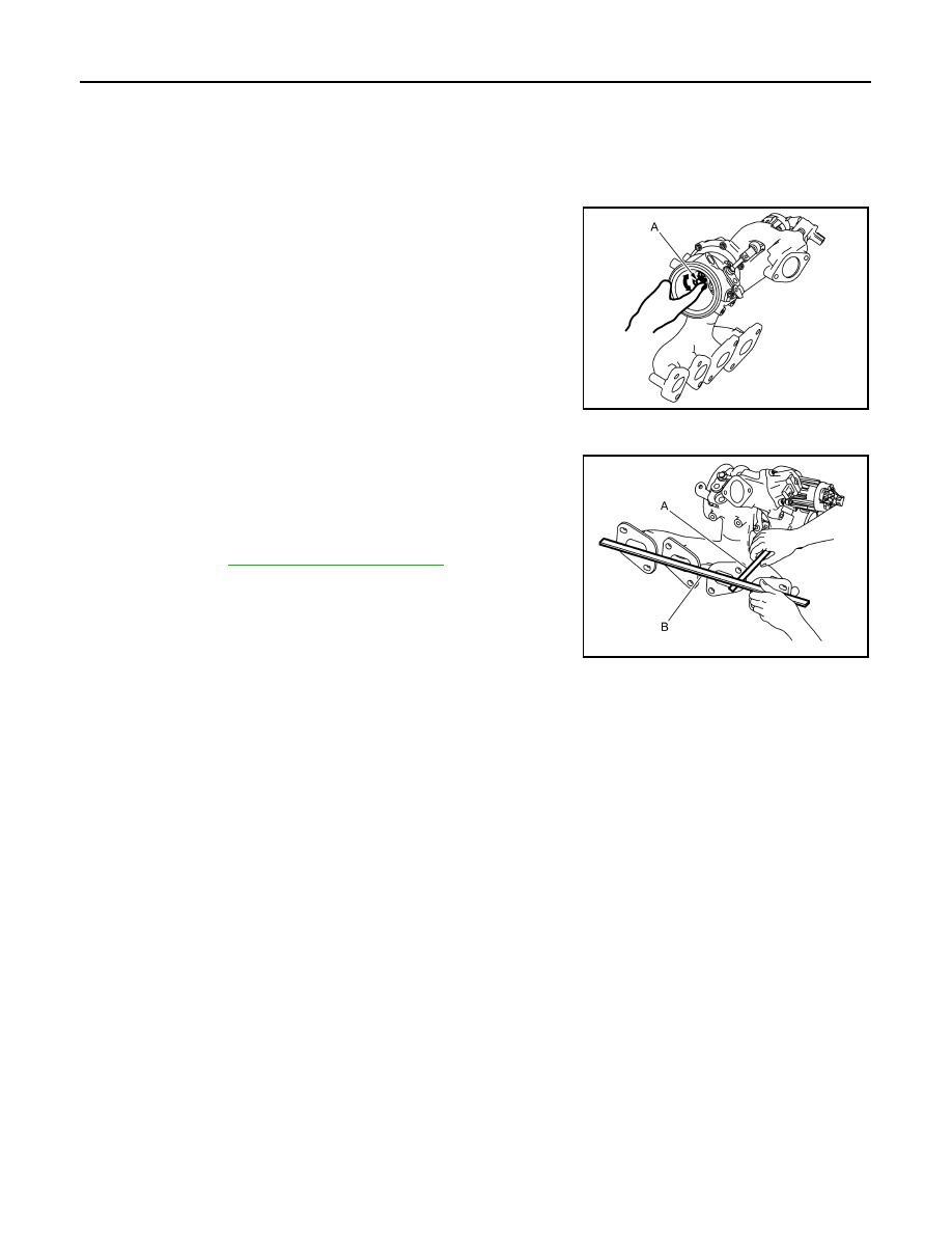
Rotor Shaft

• Rotate rotor shaft (A) by hand and check that it turns smoothly

without resistance or sticking.

• Shake rotor shaft (A) vertically and horizontally and check for

looseness.

Mounting Surface Distortion

• Using a thickness gauge (A) and straightedge (B), check for distor-

tion of the exhaust manifold and turbocharger assembly mounting

surface at each port, and for distortion of the overall assembly.

• Replace exhaust manifold and turbocharger assembly if the limit is

exceeded.

INSPECTION AFTER INSTALLATION

Start the engine and increase the engine speed. Check for engine oil leakage, exhaust gas leakage, and cool-

ant leakage.

JSBIA5789ZZ

Limit

: Refer to 

EM-312, "Exhaust Manifold"

.

JSBIA5790ZZ

EXHAUST MANIFOLD AND TURBOCHARGER ASSEMBLY

EM-247

< UNIT DISASSEMBLY AND ASSEMBLY >

[MR EXCEPT FOR NISMO RS MODELS]

C

D

E

F

G

H

I

J

K

L

M

A

EM

N

P

O

E1BIA1300GB

A. Locations to check for exhaust gas leak-

age

B. Locations to check for oil leakage

C. Locations to check for coolant leakage

D. Locations to check for air leakage

EM-248

< UNIT DISASSEMBLY AND ASSEMBLY >

[MR EXCEPT FOR NISMO RS MODELS]

TIMING CHAIN

TIMING CHAIN

Exploded View

INFOID:0000000012197428

1.

Timing chain slack guide

2.

Chain tensioner

3.

Timing chain

4.

Oil pump drive chain

5.

Crankshaft sprocket

6.

Crankshaft pulley key

7.

Oil pump sprocket

8.

Front cover

9.

Filter

JSBIA5771GB

TIMING CHAIN

EM-249

< UNIT DISASSEMBLY AND ASSEMBLY >

[MR EXCEPT FOR NISMO RS MODELS]

C

D

E

F

G

H

I

J

K

L

M

A

EM

N

P

O

Removal and Installation

INFOID:0000000012197429

CAUTION:

The rotation direction indicated in the text describes all directions as seen from engine front.

REMOVAL

1. Drain engine oil. Refer to 

LU-29, "Refilling"

.

2. Remove the following parts.

• Intake manifold: Refer to 

EM-197, "Exploded View"

.

• Rocker cover: Refer to 

EM-214, "Exploded View"

.

3. Position cylinder No. 1 at compression-stroke TDC.

• Rotate the crankshaft pulley (1) clockwise, and align the

crankshaft pulley TDC stamp line (no color) (B) with the timing

indicator (A).

• Check that the camshaft nose of cylinder No. 1 is positioned

as shown in the figure.

- If camshaft nose is not at the specified position, rotate the

crankshaft pulley one more turn.

4. Remove crankshaft pulley according to the following procedure.

10. O-ring

11. VTC cover

12.

Exhaust valve timing control solenoid 
valve

13.

Intake valve timing intermediate-lock 
control solenoid valve

14.

Intake valve timing control solenoid 
valve

15. Crankshaft pulley bolt

16. Crankshaft pulley

17. Front oil seal

18. Oil pump drive chain tensioner

19. O-ring

20. Timing chain tension guide

21. Camshaft sprocket (INT)

22. Camshaft sprocket (EXH)

23. O-ring

A.

Comply with the assembly procedure 
when tightening. Refer to 

EM-261

.

B.

Comply with the assembly procedure 
when tightening. Refer to 

EM-261

.

 : Always replace after every disassembly.

 : N·m (kg-m, ft-lb)

 : N·m (kg-m, in-lb)

 : Should be lubricated with oil.

 : Sealing point

 : Indicates that the parts is connected at points with same symbols in actual vehicle.

C

: Engraved line (white)

PBIC3960E

1

: Camshaft (INT)

2

: Camshaft (EXH)

: Engine front

JPBIA4347ZZ


Content   ..  671  672  673  674   ..