Nissan Juke F15. Manual - part 672
EM-242
< UNIT DISASSEMBLY AND ASSEMBLY >
[MR EXCEPT FOR NISMO RS MODELS]
EXHAUST MANIFOLD AND TURBOCHARGER ASSEMBLY
EXHAUST MANIFOLD AND TURBOCHARGER ASSEMBLY
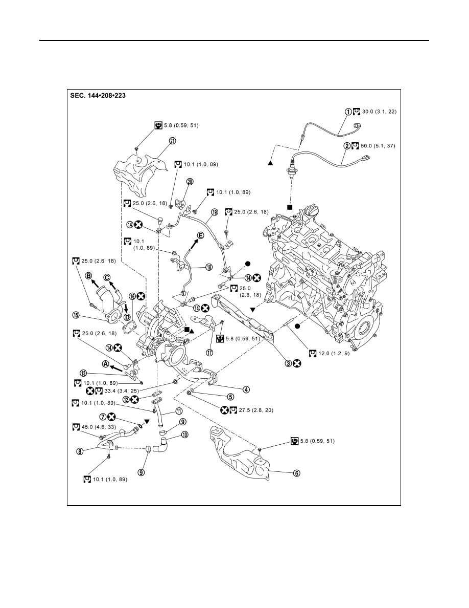
Exploded View
INFOID:0000000012197425
JSBIA5768GB
1.
Exhaust temperature sensor (Up to 3/2015)
Not applicable (From 4/2015)
2.
Air fuel ratio sensor 1
3.
Gasket
4.
Exhaust manifold and turbocharger assembly 5.
Washer
6.
Exhaust manifold cover
7.
O-ring
8.
Oil outlet tube
9.
Clamp
10. Oil outlet hose
11. Oil outlet tube
12. Gasket
13. Water outlet tube
14. Gasket
15. Turbocharger inlet tube
16. Gasket
17
Turbocharger cover lower
18. Water inlet tube