Nissan Juke F15. Manual - part 663


  Index      Nissan     Nissan Juke F15 (2015 year) - Service and Repair Manual


Search            


Content   ..  661  662  663  664   ..


Nissan Juke F15. Manual - part 663


EM-206

< REMOVAL AND INSTALLATION >

[MR EXCEPT FOR NISMO RS MODELS]

HIGH PRESSURE FUEL PUMP AND FUEL HOSE

ii.

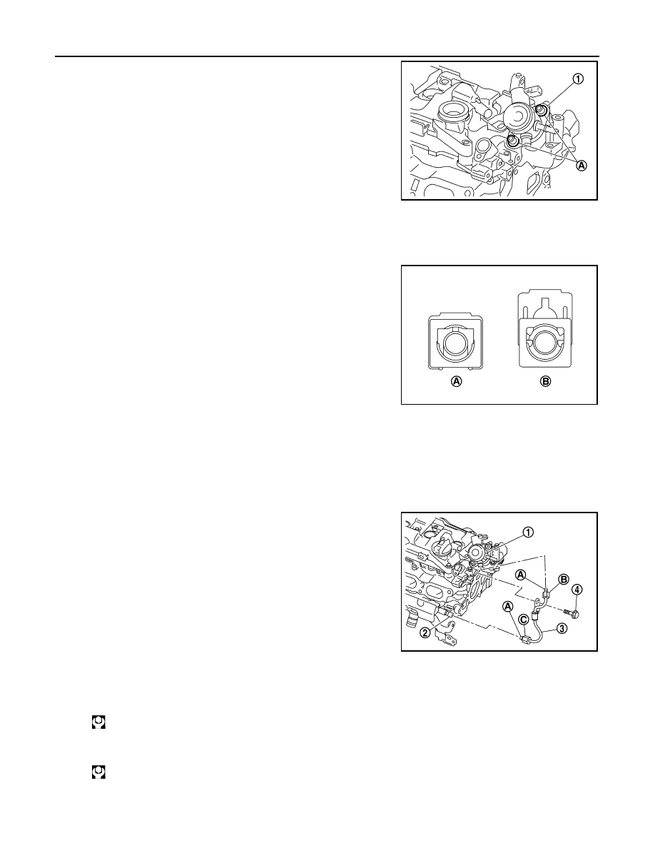
Temporarily tighten the bolts (A) by hand, and then tighten the

bolts (A) alternately one rotation at a time until the high-pressure

fuel pump flange (1) contacts the camshaft bracket.

iii. Tighten the bolts (A) to the specified torque.

2. Follow the procedure below and install the fuel feed hose.
a. Check the fuel tube and quick connector for damage or foreign material.
b. Check that the axis is lined up when inserting the quick connector into the fuel tube.
c.

Insert the retainer until a “click” sound is heard, and check that

the retainer is securely installed. Pull the quick connector by

hand and check that it is locked.

CAUTION:

If the retainer cannot be inserted smoothly, the quick con-

nector may not be connected correctly. Remove the quick

connector and then check the connection of quick connec-

tor again.

d. Secure fuel feed hose to clamp.
3. Follow the procedure below and install the high-pressure fuel tube.

CAUTION:

• Never reuse the high-pressure fuel hose. Always use a new one.

• If scratches or damage on the end of the high-pressure fuel tube are present, never use it.

• Always tighten in the correct order to the specified tightening torque.

a. Apply new engine oil to high-pressure fuel tube flare nipple (A)

and flare nuts (B),(C).

CAUTION:

Check that there is no foreign material on the high-pressure

fuel tube flare nipple and flare nuts.

b. Temporarily tighten until the high-pressure fuel tube (3) flare

nuts (B) and (C) contact the seat.

CAUTION:

When temporarily tightening the flare nuts, insert them so that they are aligned with the center of

the pipe.

c.

Tighten the high-pressure fuel tube bracket mounting bolt (4) to the specified torque.

d. Tighten flare nuts to the specified torque in the order of (B) and (C).

CAUTION:

Before tightening, check that the tool is attached at a 90

° angle to the flare nut when working.

JSBIA1673ZZ

A

: Engaged condition

B

: Not engaged condi-
tion

JPBIA4381ZZ

1

: High-pressure fuel pump

2

:  Fuel  rail

: 25.0 N·m (2.6 kg-m, 18 ft-lb)

: 36.0 N·m (3.7 kg-m, 27 ft-lb)

JSBIA6005ZZ

HIGH PRESSURE FUEL PUMP AND FUEL HOSE

EM-207

< REMOVAL AND INSTALLATION >

[MR EXCEPT FOR NISMO RS MODELS]

C

D

E

F

G

H

I

J

K

L

M

A

EM

N

P

O

e. Again tighten flare nuts to the specified torque in the order of (B) and (C).

CAUTION:

Before tightening, check that the tool is attached at a 90

° angle to the flare nut when working.

4. Note the following and install the removed parts in the reverse order of removal.

Inspection

INFOID:0000000012197395

INSPECTION AFTER INSTALLATION

Fuel Leakage Check

Check for fuel leakage according to the following procedure.
1. Turn ignition switch ON (with engine stopped). With fuel pressure applied to fuel piping, check for fuel

leakage at the locations where parts are removed and reinstalled.

NOTE:

Use a mirror or other means to check locations which cannot be seen directly.

2. Start the engine, increase the engine speed and again check for fuel leakage at the locations where parts

are removed and reinstalled.

CAUTION:

Be careful of burns when checking.

: 36.0 N·m (3.7 kg-m, 27 ft-lb)

EM-208

< REMOVAL AND INSTALLATION >

[MR EXCEPT FOR NISMO RS MODELS]

FUEL INJECTOR

FUEL INJECTOR

Exploded View

INFOID:0000000012197396

CAUTION:

Never disassemble or remove components beyond the configuration shown in the figure.

Removal and Installation

INFOID:0000000012197397

WARNING:

• Be sure to read 

EM-153, "Precaution for Handling High Pressure Fuel System"

 when working on the

high pressure fuel system.

• Put a “CAUTION: FLAMMABLE” sign in the workshop.

• Be sure to work in a well ventilated area and furnish workshop with a CO

2

 fire extinguisher. 

• Never smoke while servicing fuel system. Keep open flames and sparks away from the work area.

1.

Injector holder

2.

Seal ring (white)

3.

Backup ring

4.

O-ring (blue)

5.

Fuel injector

6.

Stud bolt

7.

Fuel rail

8.

Fuel rail insulator

9.

Fuel rail cover

10. Gasket

11. Fuel rail pressure sensor

A.

To fuel tube

B.

Comply with the assembly procedure 
when tightening. 

EM-208

.

 : Always replace after every disassembly.

 : N·m (kg-m, ft-lb)

 : N·m (kg-m, in-lb)

 : Should be lubricated with oil.

 : Indicates that the parts is connected at points with same symbols in actual vehicle.

JSBIA5911GB

FUEL INJECTOR

EM-209

< REMOVAL AND INSTALLATION >

[MR EXCEPT FOR NISMO RS MODELS]

C

D

E

F

G

H

I

J

K

L

M

A

EM

N

P

O

• To avoid the danger of being scalded, never drain engine coolant when engine is hot.

REMOVAL

1. Release fuel pressure. Refer to 

EC-771, "Work Procedure"

.

2. Remove the front bumper. Refer to 

EXT-17, "Removal and Installation"

.

3. Remove the charge air rcooler. Refer to 

EM-194, "Removal and Installation"

.

4. Remove the oil level gauge.
5. Remove the intake manifold. Refer to 

EM-197, "Removal and Installation"

.

6. Remove the alternator. Refer to 

CHG-33, "MR16DDT : Removal and Installation"

.

7. Remove the oil level gauge guide. Refer to 

EM-282, "Exploded View"

.

8. Remove the fuel rail cover and fuel rail insulator.
9. Remove the fuel tube. Refer to 

EM-203, "Exploded View"

.

CAUTION:

Because fuel leakage occurs, prepare a tray, shop cloth, and other items in advance.

10. Disconnect the fuel rail pressure sensor harness connector.
11. Disconnect the fuel injector harness connector.
12. Remove the fuel rail pressure sensor if necessary.
13. Remove the fuel rail.

• Loosen mounting bolts in the reverse order of the numerical

order shown in the figure, and remove the fuel rail.

CAUTION:

• Be careful that no parts interfere with the fuel injectors.

• Because fuel leakage occurs, prepare a tray, shop cloth,

and other items in advance.

14. Follow the procedure below and remove the fuel injector from the fuel tube.

CAUTION:

• Be careful of leakage of fuel remaining in fuel tube.

• Never damage the nozzle of fuel injector.

• Never subject parts to impact by dropping or hitting.

• Never disassemble or adjust. (Disassembly and adjustment of this part is prohibited.)

a. Remove the injector holder.
b. Install the injector remover [SST: KV10119600 ( — )] (A) with the

slit (B) aligned with the fuel injector connector.

: Engine front

JSBIA5912ZZ

JPBIA4382ZZ


Content   ..  661  662  663  664   ..