Nissan Juke F15. Manual - part 661


  Index      Nissan     Nissan Juke F15 (2015 year) - Service and Repair Manual


Search            


Content   ..  659  660  661  662   ..


Nissan Juke F15. Manual - part 661


EM-198

< REMOVAL AND INSTALLATION >

[MR EXCEPT FOR NISMO RS MODELS]

INTAKE MANIFOLD

1. Remove the engine cover. Refer to 

EM-191, "Removal and Installation"

.

2. Pull out oil level gauge.

CAUTION:

After removal, block the oil level gauge guide openings with tape so that no foreign material enters

inside engine.

3. Disconnect the turbocharger boost sensor harness connector. Refer to 

EM-194, "Exploded View"

.

4. Remove air inlet tube 1, air inlet tube 2, and the air inlet hose. Refer to 

EM-194, "Exploded View"

.

5. Disconnect the water hose from the electric throttle control actuator.

• Install a clamp or plug onto the water hose for preventing coolant leakage.

CAUTION:

Allow the engine to fully cool before starting operation.

NOTE:

This work is not necessary when only the intake manifold is removed.

6. Disconnect the harness connector from the electric throttle control actuator.
7. Remove electric throttle control actuator.

CAUTION:

• Never subject parts to impact.

• Never disassemble or adjust. (Disassembly of this part is prohibited.)

8. Disconnect the harness connector and EVAP hose from the EVAP purge volume control solenoid valve.

CAUTION:

Never subject parts to impact.

9. Disconnect the vacuum tube and vacuum hose.
10. Disconnect the PCV hose (intake manifold side).
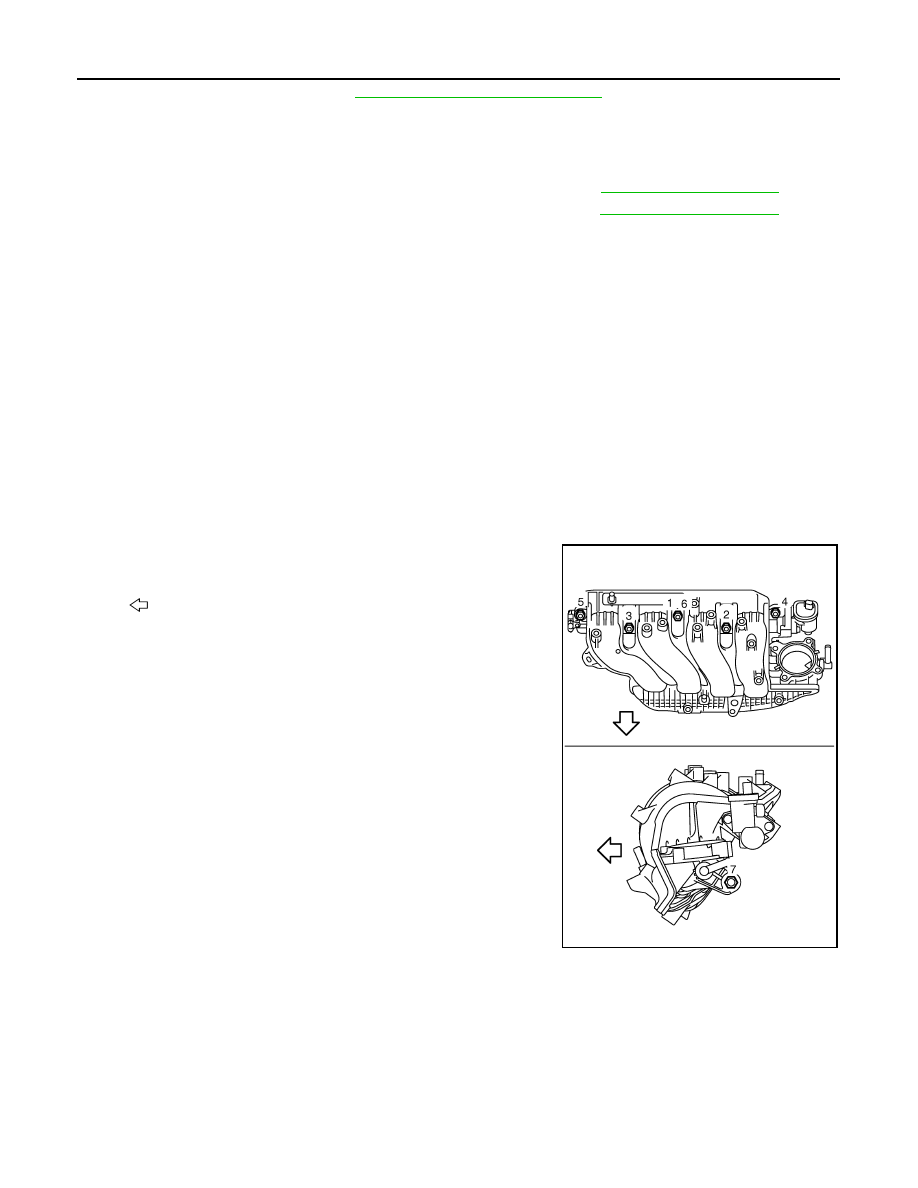
11. Follow the procedure below and remove the intake manifold.

• Loosen and remove bolts in the reverse order of the numerical

order shown in the figure.

NOTE:

Disregard the numerical order No.6 in removal.

CAUTION:

Block the openings with tape so that no foreign material

enters the engine.

12. If necessary, remove the EVAP purge control solenoid valve from the intake manifold.

CAUTION:

Never subject parts to impact.

INSTALLATION

Note the following, and install in the reverse order of removal.

Intake Manifold

1. Install the gasket to the intake manifold mounting groove.
2. Follow the procedure below and install the intake manifold.

: Vehicle front

E1BIA1279ZZ

INTAKE MANIFOLD

EM-199

< REMOVAL AND INSTALLATION >

[MR EXCEPT FOR NISMO RS MODELS]

C

D

E

F

G

H

I

J

K

L

M

A

EM

N

P

O

• Tighten the mounting bolts in the numerical order shown in the

figure.

NOTE:

• Tighten bolt the No.1 in two steps.

• The numerical order No.6 shows the second step.

3. Install in the reverse order of removal after this step.

CAUTION:

Since check valve is built-in inside vacuum hose (1), install

the vacuum hose fitting the arrow (A) to intake manifold

side (2).

Electric Throttle Control Actuator

• Tighten bolts of electric throttle control actuator equally and diagonally in several steps.

• Perform “Throttle Valve Closed Position Learning” after repair when removing harness connector of the elec-

tric throttle control actuator. Refer to 

EC-754, "Description"

.

• Perform “Throttle Valve Closed Position Learning” and “Idle Air Volume Learning” after repair when replacing

electric throttle control actuator. Refer to 

EC-754, "Description"

 and 

EC-758, "Description"

.

Inspection

INFOID:0000000012197389

INSPECTION AFTER REMOVAL

Vacuum Hose (With Check Valve)

Check the check valve. Refer to 

BR-47, "Inspection"

.

INSPECTION AFTER INSTALLATION

Run the engine while checking the installation of parts. Check for exhaust gas leakage or noise.

: Vehicle front

E1BIA1279ZZ

JPBIA4441ZZ

EM-200

< REMOVAL AND INSTALLATION >

[MR EXCEPT FOR NISMO RS MODELS]

OIL PAN (LOWER)

OIL PAN (LOWER)

Exploded View

INFOID:0000000012197390

Removal and Installation

INFOID:0000000012197391

CAUTION:

Fill with engine oil 30 minutes or more after the oil pan is installed.

1.

O-ring

2.

Oil pan (upper)

3.

Oil pump drive chain tensioner

4.

Oil pump drive chain

5.

Crankshaft sprocket

6.

Oil pump sprocket

7.

O-ring

8.

Oil pump

9.

Oil pan drain plug

10. Drain plug washer

11. Oil pan (lower)

12. O-ring

13. Oil filter

14. Oil filter stud

15. O-ring

16.

Engine oil pressure control solenoid 
valve

17. O-ring

18. Oil level gauge guide

19. Oil level gauge

20. Crankshaft position sensor

21. O-ring

22. Gasket

23. Plug

24. Rear oil seal

A.

Refer to 

LU-27

.

B.

Oil pan side

 : Always replace after every disassembly.

 : N·m (kg-m, ft-lb)

 : N·m (kg-m, in-lb)

 : Sealing point

 : Should be lubricated with oil.

,  : Indicates that the parts is connected at points with same symbols in actual vehicle.

JSBIA5724GB

OIL PAN (LOWER)

EM-201

< REMOVAL AND INSTALLATION >

[MR EXCEPT FOR NISMO RS MODELS]

C

D

E

F

G

H

I

J

K

L

M

A

EM

N

P

O

NOTE:

For the check of each part after installation, refer to 

EM-202, "Inspection"

.

REMOVAL

1. Drain engine oil. Refer to 

LU-29, "Refilling"

.

2. Remove the oil pan (lower) according to the following procedure.
a. Loosen and remove bolts in the reverse order of the numerical

order shown in the figure.

NOTE:

Disregard the numerical order No.7 and No.11 in removal.

b. Cut off the liquid gasket using a seal cutter [SST: KV10111100 (J-37228)] and remove the oil pan (lower).

CAUTION:

• Never damage the mating surface.

• Never insert a screwdriver. This damages the mating surfaces.

INSTALLATION

CAUTION:

Never reuse drain plug washer.
1. Install oil pan (lower) as follows:
a. Use a scraper (A) to remove old liquid gasket from mating sur-

faces.

• Also remove old liquid gasket from mating surface of oil pan

(upper).

• Remove old liquid gasket from the bolt holes and threads.

CAUTION:

Never scratch or damage the mating surface when cleaning

off old liquid gasket.

: Engine front

JPBIA4364GB

JPBIA4366ZZ


Content   ..  659  660  661  662   ..