Nissan Juke F15. Manual - part 625
EM-54
< REMOVAL AND INSTALLATION >
[MR FOR NISMO RS MODELS]
FUEL INJECTOR AND FUEL TUBE
FUEL INJECTOR AND FUEL TUBE
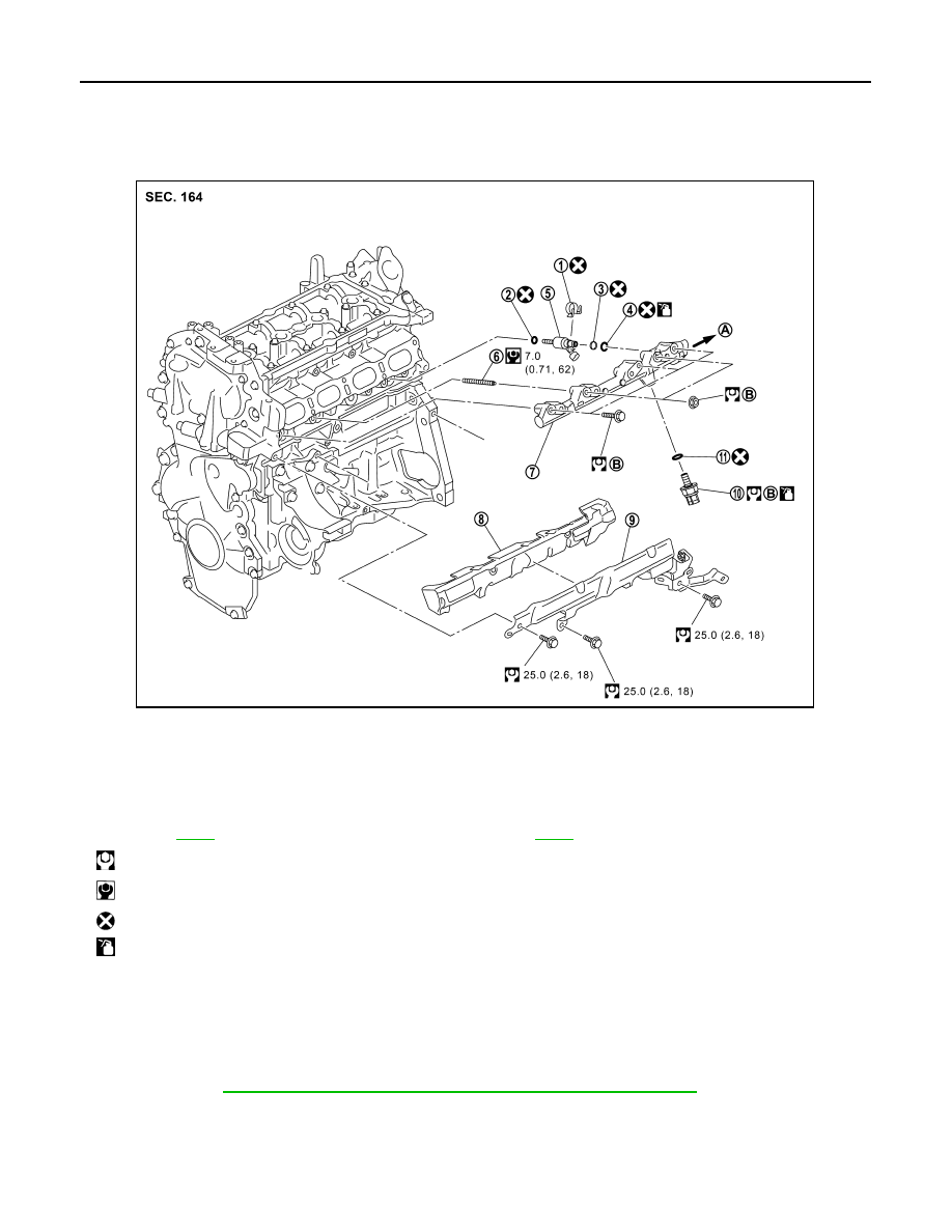
Exploded View
INFOID:0000000012197277
CAUTION:
• Never remove or disassemble parts unless instructed as shown in the figure.
Removal and Installation
INFOID:0000000012197278
WARNING:
EM-8, "Precaution for Handling High Pressure Fuel System"
when working on the
high pressure fuel system.
• Put a “CAUTION: FLAMMABLE” sign in the workshop.
• Be sure to work in a well ventilated area and furnish workshop with a CO
2
fire extinguisher.
• Never smoke while servicing fuel system. Keep open flames and sparks away from the work area.
• To avoid the danger of being scalded, never drain engine coolant when engine is hot.
1.
Holder
2.
Seal ring (white)
3.
Backup ring
4.
O-ring (blue)
5.
Fuel injector
6.
Stud bolt
7.
Fuel rail
8.
Fuel rail insulator
9.
Fuel rail cover
10. Fuel pressure sensor
11. Gasket
A.
To fuel rail connector and fuel tube.
Refer to
.
B.
Comply with the assembly procedure
when tightening. Refer to
: N·m (kg-m, ft-lb)
: N·m (kg-m, in-lb)
: Always replace after every disassembly.
: Should be lubricated with oil.
JSBIA7037GB