Nissan Juke F15. Manual - part 626


  Index      Nissan     Nissan Juke F15 (2015 year) - Service and Repair Manual


Search            


Content   ..  624  625  626  627   ..


Nissan Juke F15. Manual - part 626


EM-58

< REMOVAL AND INSTALLATION >

[MR FOR NISMO RS MODELS]

FUEL INJECTOR AND FUEL TUBE

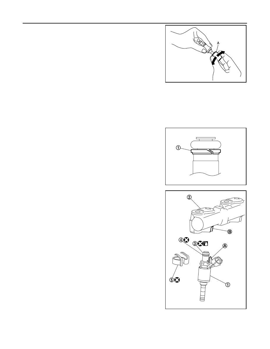
d. Insert injector seal drift set [SST: KV101197S0 (—)] (A) to injec-

tor and rotate clockwise and counterclockwise by 90

° while

pressing seal ring to fit it.

NOTE:

Compress seal ring, because this operation is for rectifying

stretch of seal ring caused by installation and for preventing

sticking when inserting injector into cylinder head.

3. Install O-ring and backup ring to fuel injector. When handing

new O-ring and backup ring, paying attention to the following

caution items:

CAUTION:

• Do not reuse O-ring.

• Handle O-ring with bare hands. Never wear gloves.

• Lubricate O-ring with new engine oil.

• Never clean O-ring with solvent.

• Check that O-ring and its mating part are free of foreign material.

• When installing O-ring, be careful not to scratch it with tool or fingernails. Also be careful not to

twist or stretch O-ring. If O-ring was stretched while it was being attached, never insert it quickly

into fuel tube.

• Insert new O-ring straight into fuel rail. Never decenter or twist it.

• Always install the back up ring (1) in the right direction as

instructed.

4. Install fuel injector (1) to fuel rail (2) as per the following:

a. Install fuel injector holder (5) to fuel injector.

CAUTION:

• Never reuse fuel injector holder. Replace it with a new

one.

• Be careful to keep fuel injector holder from interfering

with O-ring. If interference occurs, replace O-ring.

b. Insert fuel injector into fuel rail with fuel injector holder attached.

• Insert it while matching it to the axial center.

• Insert so that protrusion (A) of fuel injector is aligned to cutout

(B).

c.

Check that installation is complete by checking that fuel injector

does not rotate or come off.

• Check that protrusions of fuel injectors and fuel rail are aligned

with cutouts of clips after installation.

5. Install fuel rail and fuel injector assembly to cylinder head.

JSBIA0351ZZ

JPBIA3864ZZ

3

: O-ring (blue)

4

:  Backup  ring

JPBIA4387ZZ

FUEL INJECTOR AND FUEL TUBE

EM-59

< REMOVAL AND INSTALLATION >

[MR FOR NISMO RS MODELS]

C

D

E

F

G

H

I

J

K

L

M

A

EM

N

P

O

• Tighten mounting bolts and nuts in two steps in numerical

order as shown in the figure.

6. Connect injector harness connector.
7. Install fuel rail insulator.

CAUTION:

• As covering part of fuel tube connector at the back end of common rail can easily move because

of its shape, do not remove it before installation.

• Install the insulator so that it is placed under lower side of intake manifold flange.

8. Install in the reverse order of removal after this step.

Inspection

INFOID:0000000012197279

INSPECTION AFTER INSTALLATION

Check on Fuel Leakage

1. Turn ignition switch “ON” (with the engine stopped). With fuel pressure applied to fuel piping, check there

are no fuel leakage at connection points.

NOTE:

Use mirrors for checking at points out of clear sight.

2. Start the engine. With engine speed increased, check again that there are no fuel leakage at connection

points.

CAUTION:

Never touch the engine immediately after stopped, as the engine becomes extremely hot.

: Engine front

 1st step

: 10.0 N·m (1.0 kg-m, 89 in-lb)

 2nd step

: 20.5 N·m (2.1 kg-m, 15 ft-lb)

JPBIA4388ZZ

EM-60

< REMOVAL AND INSTALLATION >

[MR FOR NISMO RS MODELS]

IGNITION COIL, SPARK PLUG AND ROCKER COVER

IGNITION COIL, SPARK PLUG AND ROCKER COVER

Exploded View

INFOID:0000000012197280

Removal and Installation

INFOID:0000000012197281

REMOVAL

1. Drain engine coolant. Refer to 

CO-10, "Draining"

.

2. Remove engine cover. Refer to 

EM-26, "Exploded View"

.

3. Remove air inlet tube assembly. Refer to 

EM-32, "Exploded View"

.

4. Remove PCV hose.
5. Remove rocker cover protector.
6. Disconnect ignition coil harness connector, and them remove ignition coil.

CAUTION:

• Never drop or shock ignition coil.

1.

Rocker cover protector

2.

O-ring

3.

PCV control valve

4.

PCV hose

5.

Clamp

6.

Rocker cover gasket

7.

Rocker cover

8.

Clamp

9.

PCV hose

10. Oil filler cap

11. Spark plug

12. Ignition coil

A.

To intake manifold

B.

Comply with the assembly procedure 
when tightning. Refer to 

EM-60

.

C.

To air duct

 : N·m (kg-m, ft-lb)

 : N·m (kg-m, in-lb)

 : Always replace after every disassembly.

JPBIA4303GB

IGNITION COIL, SPARK PLUG AND ROCKER COVER

EM-61

< REMOVAL AND INSTALLATION >

[MR FOR NISMO RS MODELS]

C

D

E

F

G

H

I

J

K

L

M

A

EM

N

P

O

• Never disassemble ignition coil.

7. Move ignition harness.
8. Remove rocker cover.

• Loosen bolts in reverse order shown in the figure.

9. Remove PCV valve and PCV hose, if necessary.
10. Remove rocker cover gasket from rocker cover.

INSTALLATION

CAUTION:

Do not reuse O-rings.
1. Install the rocker cover gasket to rocker cover.

CAUTION:

Check the gasket is not dropped.

2. Install rocker cover.

• Tighten bolts in two steps separately in numerical order as

shown in the figure.

3. Install in the reverse order of removal, for the rest of parts. 

: Engine front

JPBIA4392ZZ

: Engine front

 1st step

: 1.96 N·m (0.20 kg-m, 17 in-lb)

 2nd step : 8.33 N·m (0.85 kg-m, 74 in-lb)

JPBIA4392ZZ


Content   ..  624  625  626  627   ..