Nissan Juke F15. Manual - part 623
EM-46
< REMOVAL AND INSTALLATION >
[MR FOR NISMO RS MODELS]
OIL PAN (LOWER)
OIL PAN (LOWER)
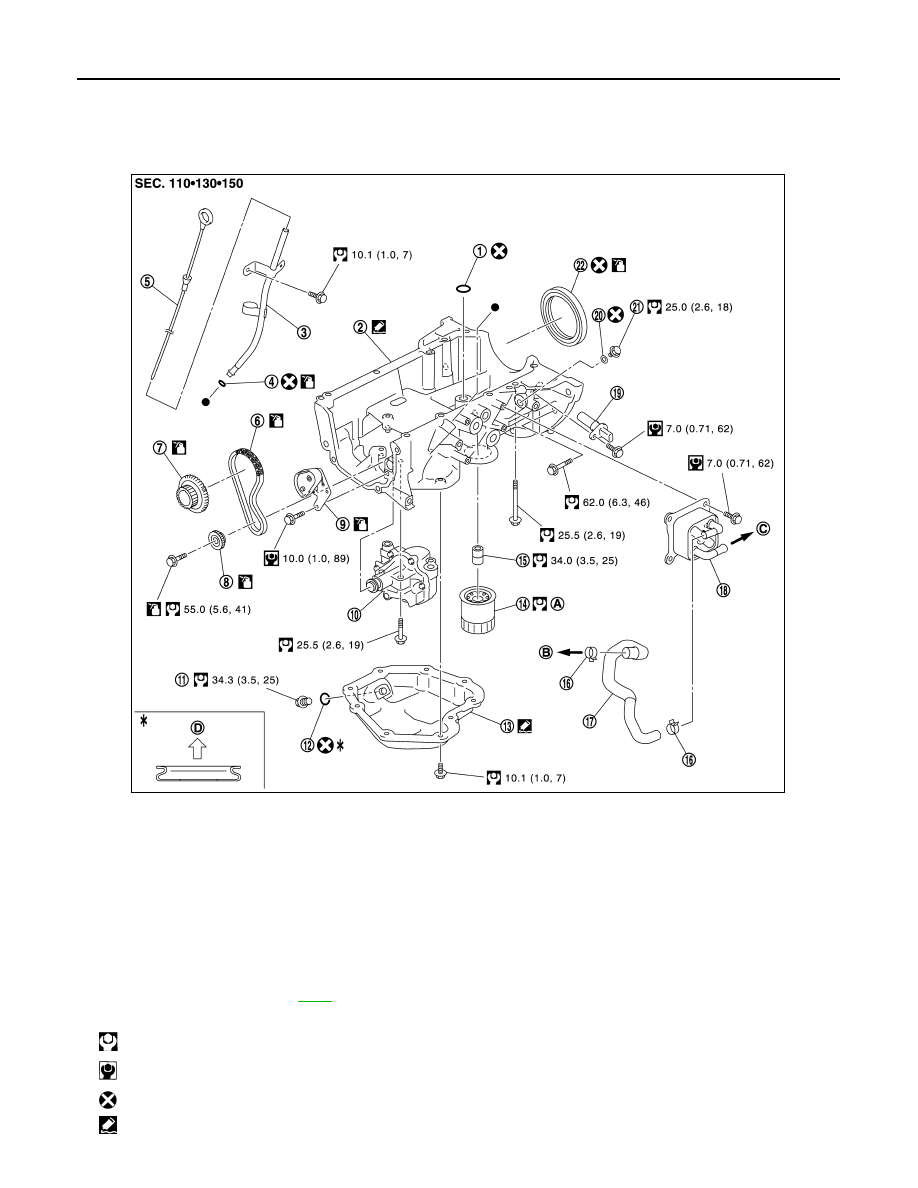
Exploded View
INFOID:0000000012197271
1.
O-ring
2.
Oil pan (upper)
3.
Oil level gauge guide
4.
O-ring
5.
Oil level gauge
6.
Oil pump drive chain
7.
Crankshaft sprocket
8.
Oil pump sprocket
9.
Oil pump chain tensioner
10. Oil pump
11. Drain plug
12. Drain plug washer
13. Oil pan (lower)
14. Oil filter
15. Connector bolt
16. Clamp 17. Water
hose
18. Oil
cooler
19. Crankshaft position sensor
20. Gasket
21. Oil pan bolt
22. Rear oil seal
A.
Comply with the assembly proce-
dure when tightening. Refer to
B.
To thermostat hosing
C.
To thermostat housing (M/T models)
To CVT oil warmer (CVT models)
D.
Oil pan side
: N·m (kg-m, ft-lb)
: N·m (kg-m, in-lb)
: Always replace after every disassembly.
: Sealing point
JPBIA4875GB