Nissan Juke F15. Manual - part 620
EM-34
< REMOVAL AND INSTALLATION >
[MR FOR NISMO RS MODELS]
CATALYST
CATALYST
2WD
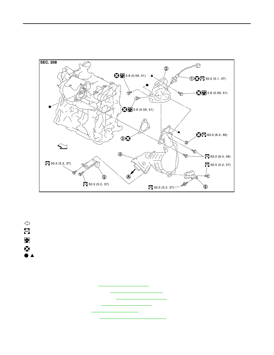
2WD : Exploded View
INFOID:0000000012197261
2WD : Removal and Installation
INFOID:0000000012197262
REMOVAL
1. Remove engine cover. Refer to
2. Remove cowl top extension. Refer to
3. Remove air duct (suction side). Refer to
4. Remove air inlet tube 3. Refer to
.
5. Remove front tube. Refer to
.
6. Remove heat insulator. Refer to
7. Remove catalyst converter support bracket (upper and lower).
8. Remove A/F sensor 1.
• Using heated oxygen sensor wrench [SST: KV10117100 (J-3647-A)], remove A/F sensor 1.
CAUTION:
JPBIA4321GB
1.
A/F sensor 1
2.
Catalyst converter shroud upper
3.
Gasket
4.
Catalyst converter
5.
Catalyst converter support bracket
(lower)
6.
Catalyst converter support bracket
(upper)
A. To exhaust system
Engine front
: N·m (kg-m, ft-lb)
: N·m (kg-m, in-lb)
: Always replace after every disassembly.
, : Indicates that the parts is connected at points with same symbols in actual vehicle.