Nissan Juke F15. Manual - part 580


  Index      Nissan     Nissan Juke F15 (2015 year) - Service and Repair Manual


Search            


Content   ..  578  579  580  581   ..


Nissan Juke F15. Manual - part 580


P2096, P2097 A/F SENSOR 1

EC-1133

< DTC/CIRCUIT DIAGNOSIS >

[MR EXCEPT FOR NISMO RS MODELS]

C

D

E

F

G

H

I

J

K

L

M

A

EC

N

P

O

3.

CHECK FOR INTAKE AIR LEAKAGE

1. Start engine and run it at idle.

2. Listen for an intake air leakage after the mass air flow sensor.
Is intake air leakage detected?

YES

>> GO TO 4.

NO

>> Repair or replace malfunctioning part.

4.

CLEAR THE MIXTURE RATIO SELF-LEARNING VALUE

1. Clear the mixture ratio self-learning value. Refer to 

EC-762, "Description"

.

2. Run engine for at least 10 minutes at idle speed.
Is the 1st trip DTC P0171 or P0172 detected? Is it difficult to start engine?

YES

>> Perform trouble diagnosis for DTC P0171 or P0172. Refer to 

EC-905, "DTC Logic"

 (P0171) or

EC-909, "DTC Logic"

 (P0172).

NO

>> GO TO 5.

5.

CHECK HARNESS CONNECTOR

1. Turn ignition switch OFF.

2. Disconnect A/F sensor 1 harness connector.

3. Check harness connector for water.

Is the inspection result normal?

YES

>> GO TO 6.

NO

>> Repair or replace harness connector.

6.

CHECK AIR FUEL RATIO (A/F) SENSOR 1 POWER SUPPLY

1. Disconnect A/F sensor 1 harness connector.

2. Turn ignition switch ON.

3. Check the voltage between A/F sensor 1 harness connector and ground.

Is the inspection result normal?

YES

>> GO TO 8.

NO

>> GO TO 7.

7.

CHECK AIR FUEL RATIO (A/F) SENSOR 1 POWER SUPPLY CIRCUIT

1. Turn ignition switch OFF.

2. Disconnect IPDM E/R harness connector.

3. Check the continuity between A/F sensor 1 harness connector and IPDM E/R harness connector.

Is the inspection result normal?

YES

>> Perform the trouble diagnosis for power supply circuit.

NO

>> Repair or replace error-detected parts.

8.

CHECK A/F SENSOR 1 INPUT SIGNAL CIRCUIT FOR OPEN AND SHORT

1. Turn ignition switch OFF.

2. Disconnect ECM harness connector.

3. Check the continuity between A/F sensor 1 harness connector and ECM harness connector.

Water should not exit.
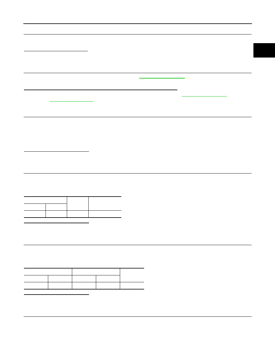
A/F sensor

Ground

Voltage (V)

Connector

Terminal

F72

4

Ground

Battery voltage

A/F sensor 1

IPDM E/R 

Continuity

Connector

Terminal

Connector

Terminal

F72

4

E14

36

Existed

EC-1134

< DTC/CIRCUIT DIAGNOSIS >

[MR EXCEPT FOR NISMO RS MODELS]

P2096, P2097 A/F SENSOR 1

4. Check the continuity between A/F sensor 1 harness connector and ground, or ECM harness connector

and ground.

5. Also check harness for short to power.
Is the inspection result normal?

YES

>> GO TO 9.

NO

>> Repair open circuit, short to ground or short to power in harness or connectors.

9.

CHECK A/F SENSOR 1 HEATER

Check A/F sensor 1 heater. Refer to 

EC-806, "Component Inspection"

.

Is the inspection result normal?

YES

>> GO TO 10.

NO

>> GO TO 12.

10.

CHECK HEATED OXYGEN SENSOR 2

Check heated oxygen sensor 2. Refer to 

EC-884, "Component Inspection"

.

Is the inspection result normal?

YES

>> GO TO 11.

NO

>> Replace malfunctioning heated oxygen sensor 2.

11.

CHECK INTERMITTENT INCIDENT

Check intermittent incident. Perform 

GI-45, "Intermittent Incident"

.

Is the inspection result normal?

YES

>> GO TO 12.

NO

>> Repair or replace malfunctioning part.

12.

REPLACE AIR FUEL RATIO (A/F) SENSOR 1

Replace malfunctioning air fuel ratio (A/F) sensor 1. Refer to 

EM-242, "Exploded View"

.

Do you have CONSULT?

YES

>> GO TO 13.

NO

>> GO TO 14.

13.

CONFIRM A/F ADJUSTMENT DATA

With CONSULT

1. Turn ignition switch ON.

2. Select “A/F ADJ-B1” in “DATA MONITOR” mode with CONSULT.

3. Make sure that “0.000” is displayed on CONSULT screen.
Is “0.000” displayed?

YES

>> INSPECTION END

A/F sensor 1

ECM

Continuity

Connector

Terminal

Connector

Terminal

F72

1

F24

79

Existed

2

74

A/F sensor 1

Ground

Continuity

Connector

Terminal

F72

1

Ground

Not existed

2

ECM

Ground

Continuity

Connector

Terminal

F24

74

Ground

Not existed

79

P2096, P2097 A/F SENSOR 1

EC-1135

< DTC/CIRCUIT DIAGNOSIS >

[MR EXCEPT FOR NISMO RS MODELS]

C

D

E

F

G

H

I

J

K

L

M

A

EC

N

P

O

NO

>> GO TO 14.

14.

CLEAR THE MIXTURE RATIO SELF-LEARNING VALUE

Clear the mixture ratio self-learning value. Refer to 

EC-762, "Description"

.

Do you have CONSULT?

YES

>> GO TO 15.

NO

>> INSPECTION END

15.

CONFIRM A/F ADJUSTMENT DATA

With CONSULT

1. Turn ignition switch ON.

2. Select “A/F ADJ-B1” in “DATA MONITOR” mode with CONSULT.

3. Make sure that “0.000” is displayed on CONSULT screen.

>> INSPECTION END

EC-1136

< DTC/CIRCUIT DIAGNOSIS >

[MR EXCEPT FOR NISMO RS MODELS]

P2100, P2103 THROTTLE CONTROL MOTOR RELAY

P2100, P2103 THROTTLE CONTROL MOTOR RELAY

DTC Logic

INFOID:0000000012198659

DTC DETECTION LOGIC

DTC CONFIRMATION PROCEDURE

1.

PRECONDITIONING

If DTC Confirmation Procedure has been previously conducted, always perform the following procedure

before conducting the next test.

1. Turn ignition switch OFF and wait at least 10 seconds.

2. Turn ignition switch ON.

3. Turn ignition switch OFF and wait at least 10 seconds.

TESTING CONDITION:

Before performing the following procedure, confirm that battery voltage is more than 8 V.
Witch DTC is detected?

P2100 >> GO TO 2.

P2103 >> GO TO 3.

2.

PERFORM DTC CONFIRMATION PROCEDURE FOR DTC P2100

1. Turn ignition switch ON and wait at least 2 seconds.

2. Start engine and let it idle for 5 seconds.

3. Check DTC.
Is DTC detected?

YES

>> Proceed to 

EC-1136, "Diagnosis Procedure"

.

NO

>> INSPECTION END

3.

PERFORM DTC CONFIRMATION PROCEDURE FOR DTC P2103

1. Turn ignition switch ON and wait at least 1 second.

2. Check DTC.
Is DTC detected?

YES

>> Proceed to 

EC-1136, "Diagnosis Procedure"

.

NO

>> INSPECTION END

Diagnosis Procedure

INFOID:0000000012198660

1.

CHECK THROTTLE CONTROL MOTOR RELAY POWER SUPPLY

1. Turn ignition switch OFF.

2. Check the voltage between ECM harness connector and ground.

DTC No.

Trouble diagnosis name

(Trouble diagnosis con-

tent)

DTC detecting condition

Possible cause

P2100

ETC MOT PWR-B1
(Throttle control motor 
relay circuit open)

ECM detects a voltage of power source for 
throttle control motor is excessively low.

• Harness or connectors

(Throttle control motor relay circuit is 
open)

• Throttle control motor relay

P2103

ETC MOT PWR
(Throttle control motor 
relay circuit short)

ECM detect the throttle control motor relay is 
stuck ON.

• Harness or connectors

(Throttle control motor relay circuit is 
shorted)

• Throttle control motor relay

+

Voltage

ECM

Connector

Terminal

Connector

Terminal

F24

97

E19

152

Battery voltage


Content   ..  578  579  580  581   ..