Nissan Juke F15. Manual - part 578


  Index      Nissan     Nissan Juke F15 (2015 year) - Service and Repair Manual


Search            


Content   ..  576  577  578  579   ..


Nissan Juke F15. Manual - part 578


P1805 BRAKE SWITCH

EC-1125

< DTC/CIRCUIT DIAGNOSIS >

[MR EXCEPT FOR NISMO RS MODELS]

C

D

E

F

G

H

I

J

K

L

M

A

EC

N

P

O

Is the inspection result normal?

YES

>> GO TO 3.

NO

>> Repair or replace error-detected parts.

3.

CHECK STOP LAMP SWITCH

Check the stop lamp switch. Refer to 

EC-1125, "Component Inspection (Stop Lamp Switch)"

.

Is the inspection result normal?

YES

>> Check intermittent incident. Refer to 

GI-45, "Intermittent Incident"

.

NO

>> Replace stop lamp switch. Refer to 

BR-20, "Exploded View"

.

Component Inspection (Stop Lamp Switch)

INFOID:0000000012198649
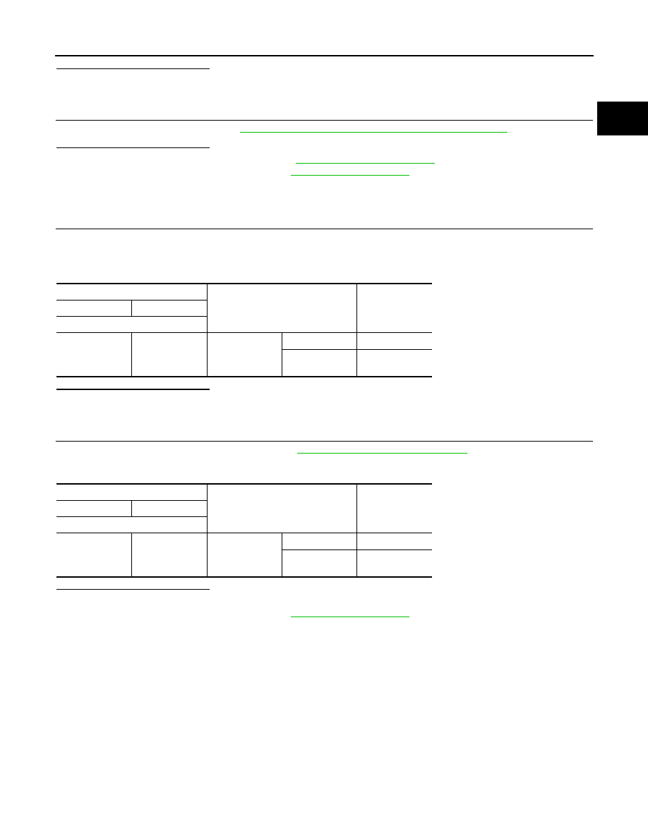
1.

CHECK STOP LAMP SWITCH-I

1. Turn ignition switch OFF.

2. Disconnect stop lamp switch harness connector.

3. Check the continuity between stop lamp switch terminals as per the following conditions.

Is the inspection result normal?

YES

>> INSPECTION END

NO

>> GO TO 2.

2.

CHECK STOP LAMP SWITCH-II

1. Adjust stop lamp switch installation. Refer to 

BR-9, "Inspection and Adjustment"

.

2. Check the continuity between stop lamp switch terminals as per the following conditions.

Is the inspection result normal?

YES

>> INSPECTION END

NO

>> Replace stop lamp switch. Refer to 

BR-20, "Exploded View"

.

Stop lamp switch

Condition

Continuity

+

-

Terminals

1

 2

Brake pedal

Fully released

Not existed

Slightly de-
pressed

Existed

Stop lamp switch

Condition

Continuity

+

-

Terminals

1

 2

Brake pedal

Fully released

Not existed

Slightly de-
pressed

Existed

EC-1126

< DTC/CIRCUIT DIAGNOSIS >

[MR EXCEPT FOR NISMO RS MODELS]

P2004 INTAKE MANIFOLD RUNNER CONTROL VALVE

P2004 INTAKE MANIFOLD RUNNER CONTROL VALVE

DTC Logic

INFOID:0000000012198650

DTC DETECTION LOGIC

DTC CONFIRMATION PROCEDURE

1.

PRECONDITIONING

If DTC Confirmation Procedure has been previously conducted, always turn ignition switch OFF and wait at

least 10 seconds before conducting the next test.

TESTING CONDITION:

• Before performing the following procedure, confirm that battery voltage is more than 11 V at idle.

• Always perform the test at a temperature above 

−12°C (10°F)

>> GO TO 2.

2.

PERFORM DTC CONFIRMATION PROCEDURE

With CONSULT

1. Turn ignition switch ON.

2. Select “DATA MONITOR” mode using CONSULT.

3. Make sure that “COOLANT TEMP/S” indicates 5

°C (41°F) or more.

If not, cool engine down or warm engine up until “COOLANT TEMP/S” indicates 5

°C (41°F) or more. Then

go to the following steps.

4. Fully release accelerator pedal and wait at least 10 seconds.

5. Depress accelerator pedal and wait at least 10 seconds.

6. Check 1st trip DTC.

With GST

Following the procedure “With CONSULT” above.
Is 1st trip DTC detected?

YES

>> Proceed to 

EC-1126, "Diagnosis Procedure"

.

NO

>> INSPECTION END

Diagnosis Procedure

INFOID:0000000012198651

1.

CHECK INTAKE MANIFOLD RUNNER CONTROL VALVE POWER SUPPLY

1. Turn ignition switch ON.

2. Check the voltage between ECM harness connector.

Is the inspection result normal?

YES

>> GO TO 3.

NO

>> GO TO 2.

2.

CHECK INTAKE MANIFOLD RUNNER CONTROL VALVE POWER SUPPLY CIRCUIT

DTC No.

CONSULT screen terms

(Trouble diagnosis content)

DTC detecting condition

Possible cause

P2004

TUMBLE CONT/V
(Intake manifold runner control 
stuck open bank 1)

The target angle of intake manifold runner 
control valve controlled by ECM and the in-
put signal from intake manifold runner con-
trol valve position sensor is not in the 
normal range.

• Harness or connectors

(Intake manifold runner control valve cir-
cuit is open or shorted.)

• Intake manifold runner control valve
• Intake manifold runner control valve is 

stuck

ECM

Voltage

+

-

Connector

Terminal

Connector

Terminal

F23

53

E19

152

Battery voltage

P2004 INTAKE MANIFOLD RUNNER CONTROL VALVE

EC-1127

< DTC/CIRCUIT DIAGNOSIS >

[MR EXCEPT FOR NISMO RS MODELS]

C

D

E

F

G

H

I

J

K

L

M

A

EC

N

P

O

1. Turn ignition switch OFF.

2. Disconnect ECM harness connector.

3. Disconnect IPDM E/R harness connector.

4. Check the continuity between ECM harness connector and IPDM E/R harness connector.

5. Also check harness for short to ground.
Is the inspection result normal?

YES

>> Perform the trouble diagnosis for power supply circuit.

NO

>> Repair or replace error-detected parts.

3.

CHECK INTAKE MANIFOLD RUNNER CONTROL VALVE OUTPUT SIGNAL CIRCUIT

1. Disconnect intake manifold runner control valve harness connector.

2. Check the continuity between intake manifold runner control valve harness connector and ECM harness

connector.

3. Also check harness for short to ground and to power.
Is the inspection result normal?

YES

>> GO TO 4.

NO

>> Repair or replace error-detected parts.

4.

CHECK INTAKE MANIFOLD RUNNER CONTROL VALVE

Check the intake manifold runner control valve. Refer to 

EC-1127, "Component Inspection (Intake Manifold

Runner Control Valve)"

.

Is the inspection result normal?

YES

>> Check intermittent incident. Refer to 

GI-45, "Intermittent Incident"

.

NO

>> Replace intake manifold assembly. Refer to 

EM-197, "Removal and Installation"

.

Component Inspection (Intake Manifold Runner Control Valve)

INFOID:0000000012198652

1.

CHECK INTAKE MANIFOLD RUNNER CONTROL VALVE

 With CONSULT

1. Turn ignition switch ON.

2. Select “DATA MONITOR” mode with CONSULT.

3. Make sure that “COOLAN TEMP/S” indicates between 

−12°C (10°F) to 59°C (138°F).

If not, cool engine down or warm engine up until “COOLAN TEMP/S” indicates between 

−12°C (10°F) to

59

°C (138°F). Then go to the following steps.

4. Fully release accelerator pedal and make sure that “TUMBLE POS SEN” indicates between 2.8 V to 4.1

V.

5. Depress accelerator pedal and make sure that “TUMBLE POS SEN” indicates between 0.2 V to 1.4 V.

6. Check 1st trip DTC.

 With GST

Following the procedure “With CONSULT” above.

+

Continuity

ECM

IPDM E/R

Connector

Terminal

Connector

Terminal

F23

53

E14

36

Existed

+

Continuity

Intake manifold runner con-

trol valve

ECM

Connector

Terminal

Connector

Terminal

F59

1

F23

54

Existed

55

Not existed

2

54

Not existed

55

Existed

EC-1128

< DTC/CIRCUIT DIAGNOSIS >

[MR EXCEPT FOR NISMO RS MODELS]

P2004 INTAKE MANIFOLD RUNNER CONTROL VALVE

Is 1st trip DTC detected?

YES

>> Replace intake manifold assembly. Refer to 

EM-197, "Removal and Installation"

.

NO

>> GO TO 2.

2.

CHECK INTAKE MANIFOLD RUNNER CONTROL VALVE

1. Turn ignition switch OFF.

2. Disconnect intake manifold runner control valve harness connector.

3. Check the resistance between intake manifold runner control valve terminals as per the following.

Is the inspection result normal?

YES

>> INSPECTION END

NO

>> Replace intake manifold assembly. Refer to 

EM-197, "Removal and Installation"

.

Intake manifold runner control valve

Resistance

(Approx.)

+

Terminals

1

2

3 - 8 

Ω [at 25°C (77°F)]


Content   ..  576  577  578  579   ..