Nissan Juke F15. Manual - part 581
P2100, P2103 THROTTLE CONTROL MOTOR RELAY
EC-1137
< DTC/CIRCUIT DIAGNOSIS >
[MR EXCEPT FOR NISMO RS MODELS]
C
D
E
F
G
H
I
J
K
L
M
A
EC
N
P
O
Is the inspection result normal?
YES
>> GO TO 3.
NO
>> GO TO 2.
2.
CHECK THROTTLE CONTROL MOTOR RELAY POWER SUPPLY CIRCUIT
1. Disconnect ECM harness connector.
2. Disconnect IPDM E/R harness connector.
3. Check the continuity between ECM harness connector and IPDM E/R harness connector.
4. Also check harness for short to ground.
Is the inspection result normal?
YES
>> Perform the trouble diagnosis for power supply circuit.
NO
>> Repair or replace error-detected parts.
3.
CHECK THROTTLE CONTROL MOTOR RELAY INPUT SIGNAL
Check the voltage between ECM harness connector and ground as per the following conditions.
Is the inspection result normal?
YES
>> Check intermittent incident. Refer to
GI-45, "Intermittent Incident"
.
NO
>> GO TO 4.
4.
CHECK THROTTLE CONTROL MOTOR RELAY INPUT SIGNAL CIRCUIT
1. Turn ignition switch OFF.
2. Disconnect ECM harness connector.
3. Disconnect IPDM E/R harness connector.
4. Check the continuity between ECM harness connector and IPDM E/R harness connector.
5. Also check harness for short to ground and to power.
Is the inspection result normal?
YES
>> Check intermittent incident. Refer to
GI-45, "Intermittent Incident"
.
NO
>> Repair or replace error-detected parts.
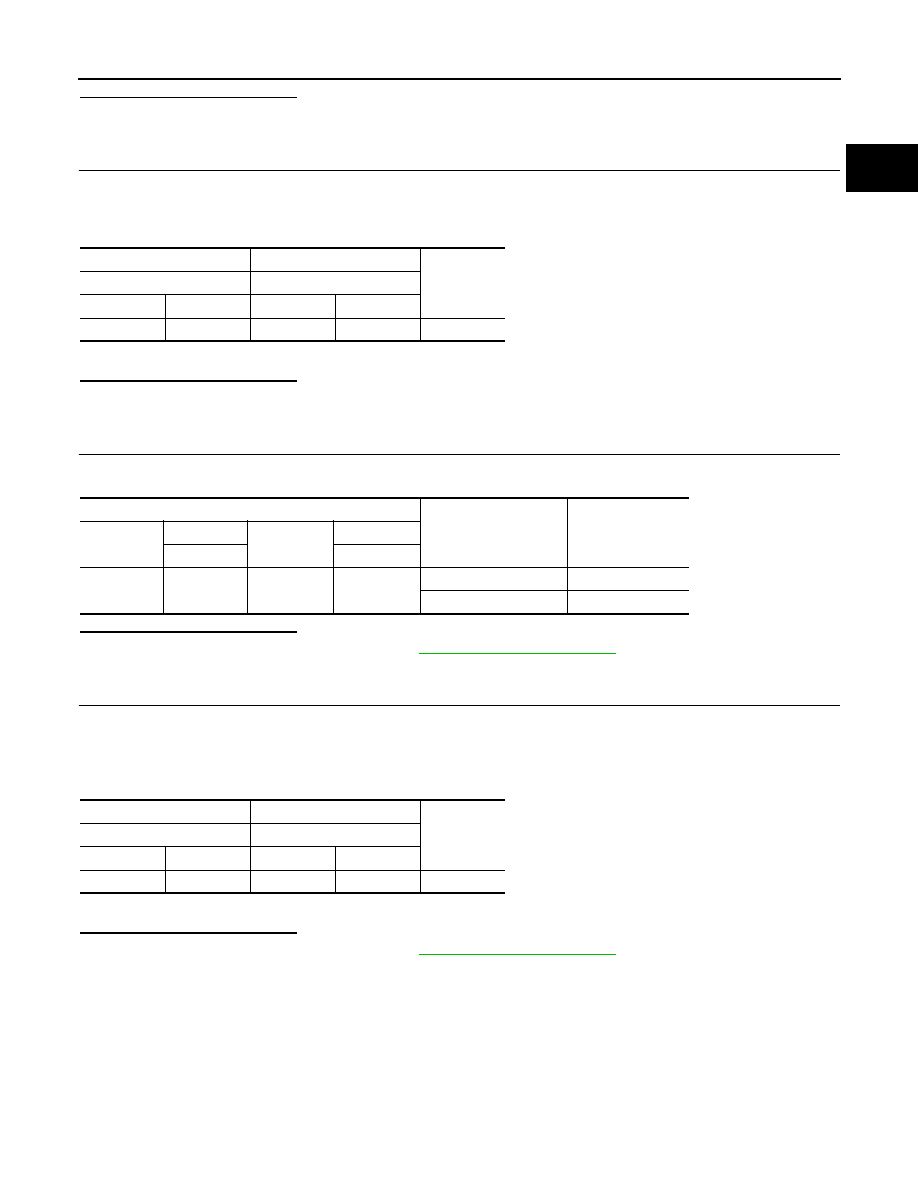
+
−
Continuity
ECM
IPDM E/R
Connector
Terminal
Connector
Terminal
F24
97
E15
60
Existed
ECM
Condition
Voltage
(Approx.)
Connector
+
Connector
−
Terminal
Terminal
F24
118
E19
152
Ignition switch: OFF
0 V
Ignition switch: ON
Battery voltage
+
−
Continuity
ECM
IPDM E/R
Connector
Terminal
Connector
Terminal
F24
118
E15
55
Existed