Nissan Juke F15. Manual - part 563


  Index      Nissan     Nissan Juke F15 (2015 year) - Service and Repair Manual


Search            


Content   ..  561  562  563  564   ..


Nissan Juke F15. Manual - part 563


P0850 PNP SWITCH

EC-1065

< DTC/CIRCUIT DIAGNOSIS >

[MR EXCEPT FOR NISMO RS MODELS]

C

D

E

F

G

H

I

J

K

L

M

A

EC

N

P

O

P0850 PNP SWITCH

Description

INFOID:0000000012198581

For CVT models, transmission range switch is turn ON when the selector lever is P or N.

For M/T models, park/neutral position (PNP) range switch is ON when the selector lever is Neutral position.

ECM detects the position because the continuity of the line (the ON) exists.

DTC Logic

INFOID:0000000012198582

DTC DETECTION LOGIC

DTC CONFIRMATION PROCEDURE

1.

INSPECTION START

Do you have CONSULT?

YES

>> GO TO 2.

NO

>> GO TO 5.

2.

PRECONDITIONING

If DTC Confirmation Procedure has been previously conducted, always perform the following procedure

before conducting the next test. 

1. Turn ignition switch OFF and wait at least 10 seconds.

2. Turn ignition switch ON.

3. Turn ignition switch OFF and wait at least 10 seconds.

>> GO TO 3.

3.

CHECK PNP SIGNAL FUNCTION

With CONSULT

1. Turn ignition switch ON.

2. Select “P/N POSI SW” in “DATA MONITOR” mode of “ENGINE” using CONSULT. Then check the “P/N

POSI SW” signal as per the following conditions.

Is the inspection result normal?

YES

>> GO TO 4.

NO

>> Proceed to 

EC-1066, "Diagnosis Procedure"

.

4.

PERFORM DTC CONFIRMATION PROCEDURE

1. Select “DATA MONITOR” mode of “ENGINE” using CONSULT.

2. Start engine and warm it up to normal operating temperature.

DTC No.

Trouble diagnosis name

(Trouble diagnosis content)

DTC detecting condition

Possible cause

P0850

P-N POS SW/CIRCUIT
(Park/neutral position 
switch)

• For CVT models, the signal of transmis-

sion range switch is not changed in the 
process of engine starting and driving.

• For M/T models, the signal of the park/

neutral position (PNP) switch is not 
changed in the process of engine starting 
and driving.

• Harness or connectors

[The transmission range switch circuit is 
open or shorted.(CVT models)]
[The park/neutral position (PNP) switch 
circuit is open or shorted.(M/T models)]

• Transmission range switch (CVT mod-

els)

• Park/neutral position (PNP) switch (M/T 

models)

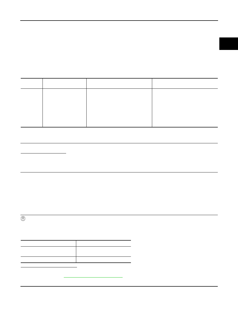
Selector lever position

Known-good signal

N or P position (CVT)
Neutral position (M/T)

ON

Except above position

OFF

EC-1066

< DTC/CIRCUIT DIAGNOSIS >

[MR EXCEPT FOR NISMO RS MODELS]

P0850 PNP SWITCH

3. Maintain the following conditions for at least 60 consecutive seconds.

CAUTION:

Always drive vehicle at a safe speed.

4. Check 1st trip DTC.
Is 1st trip DTC detected?

YES

>> Proceed to 

EC-1066, "Diagnosis Procedure"

.

NO

>> INSPECTION END

5.

PERFORM COMPONENT FUNCTION CHECK

Perform component function check. Refer to 

EC-1066, "Component Function Check"

.

NOTE:

Use component function check the overall function of the transmission range switch circuit (CVT models) or

the park/neutral position (PNP) switch circuit (M/T models). During this check, a 1st trip DTC might not be con-

firmed.
Is the inspection result normal?

YES

>> INSPECTION END

NO

>> Proceed to 

EC-1066, "Diagnosis Procedure"

.

Component Function Check

INFOID:0000000012198583

1.

PERFORM COMPONENT FUNCTION CHECK

1. Turn ignition switch ON.

2. Check the voltage between ECM harness connector and ground as per the following conditions.

Is the inspection result normal?

YES

>> INSPECTION END

NO

>> Proceed to 

EC-1066, "Diagnosis Procedure"

.

Diagnosis Procedure

INFOID:0000000012198584

1.

INSPECTION START

Check which type of transmission the vehicle is equipped with.
Which type of transmission?

CVT

>> GO TO 2.

M/T

>> GO TO 6.

2.

CHECK TRANSMISSION RANGE SWITCH POWER SUPPLY

1. Turn ignition switch OFF.

2. Disconnect transmission range switch harness connector.

3. Turn ignition switch ON.

ENG SPEED

1,125 - 6,375 rpm (CVT)
1,820 - 6,375 rpm (M/T)

COOLAN TEMP/S

More than 70

°C (158°F)

B/FUEL SCHDL

3.3 - 31.8 msec (CVT)
1.2 - 31.8 msec (M/T)

VHCL SPEED SE

More than 64 km/h (40 mph)

Selector lever

Suitable position

ECM

Condition

Voltage

(Approx.)

Connector

+

Connector

Terminal

Terminal

F24

103

E19

152

Selector lever

P or N (CVT)
Neutral (M/T)

0 V

Except above

Battery voltage

P0850 PNP SWITCH

EC-1067

< DTC/CIRCUIT DIAGNOSIS >

[MR EXCEPT FOR NISMO RS MODELS]

C

D

E

F

G

H

I

J

K

L

M

A

EC

N

P

O

4. Check the voltage between transmission range switch harness connector and ground.

Is the inspection result normal?

YES

>> GO TO 4.

NO

>> GO TO 3.

3.

CHECK TRANSMISSION RANGE SWITCH POWER SUPPLY CIRCUIT

1. Turn ignition switch OFF.

2. Disconnect IPDM E/R harness connector.

3. Check the continuity between transmission range switch harness connector and IPDM E/R harness con-

nector.

4. Also check harness for short to ground.
Is the inspection result normal?

YES

>> Perform the trouble diagnosis for power supply circuit.

NO

>> Repair or replace error-detected parts.

4.

CHECK TRANSMISSION RANGE SWITCH SIGNAL CIRCUIT

1. Turn ignition switch OFF.

2. Disconnect ECM harness connector.

3. Check the continuity between transmission range switch harness connector and ECM harness connector.

4. Also check harness for short to ground and to power.
Is the inspection result normal?

YES

>> GO TO 5.

NO

>> Repair or replace error-detected parts.

5.

CHECK TRANSMISSION RANGE SWITCH

Check the transmission range switch. Refer to 

TM-458, "Component Inspection"

.

Is the inspection result normal?

YES

>> Check intermittent incident. Refer to 

GI-45, "Intermittent Incident"

.

NO

>> Replace transmission range switch. Refer to 

TM-577, "Removal and Installation"

.

6.

CHECK PARK/NEUTRAL POSITION (PNP) SWITCH POWER SUPPLY

1. Turn ignition switch OFF.

2. Disconnect PNP switch harness connector.

3. Turn ignition switch ON.

4. Check the voltage between PNP switch harness connector and ground.

+

Voltage

Transmission range switch

Connector

Terminal

F30

1

Ground

Battery voltage

+

Continuity

Transmission range switch

IPDM E/R

Connector

Terminal

Connector

Terminal

F30

1

E15

58

Existed

+

Continuity

Transmission range switch

ECM

Connector

Terminal

Connector

Terminal

F30

2

F24

103

Existed

EC-1068

< DTC/CIRCUIT DIAGNOSIS >

[MR EXCEPT FOR NISMO RS MODELS]

P0850 PNP SWITCH

Is the inspection result normal?

YES

>> GO TO 7.

NO

>> Perform the trouble diagnosis for power supply circuit.

7.

CHECK PNP SWITCH INPUT SIGNAL CIRCUIT

1. Turn ignition switch OFF.

2. Disconnect ECM harness connector.

3. Check the continuity between PNP switch harness connector and ECM harness connector.

4. Also check harness for short to ground and to power.
Is the inspection result normal?

YES

>> GO TO 8.

NO

>> Repair or replace error-detected parts.

8.

CHECK PNP SWITCH

Check the PNP switch. Refer to 

TM-20, "PARK/NEUTRAL POSITION (PNP) SWITCH : Component Inspec-

tion"

.

Is the inspection result normal?

YES

>> Check intermittent incident. Refer to 

GI-45, "Intermittent Incident"

.

NO

>> Replace PNP switch. Refer to 

TM-24, "Removal and Installation"

.

+

Voltage

PNP switch

Connector

Terminal

F49

2

Ground

Battery voltage

+

Continuity

PNP switch

ECM

Connector

Terminal

Connector

Terminal

F49

3

F24

103

Existed


Content   ..  561  562  563  564   ..