Nissan Juke F15. Manual - part 546
P044B EXHAUST GAS RECIRCULATION SYSTEM
EC-997
< DTC/CIRCUIT DIAGNOSIS >
[MR EXCEPT FOR NISMO RS MODELS]
C
D
E
F
G
H
I
J
K
L
M
A
EC
N
P
O
Is the inspection result normal?
YES
>> GO TO 2.
NO
>> GO TO 5.
2.
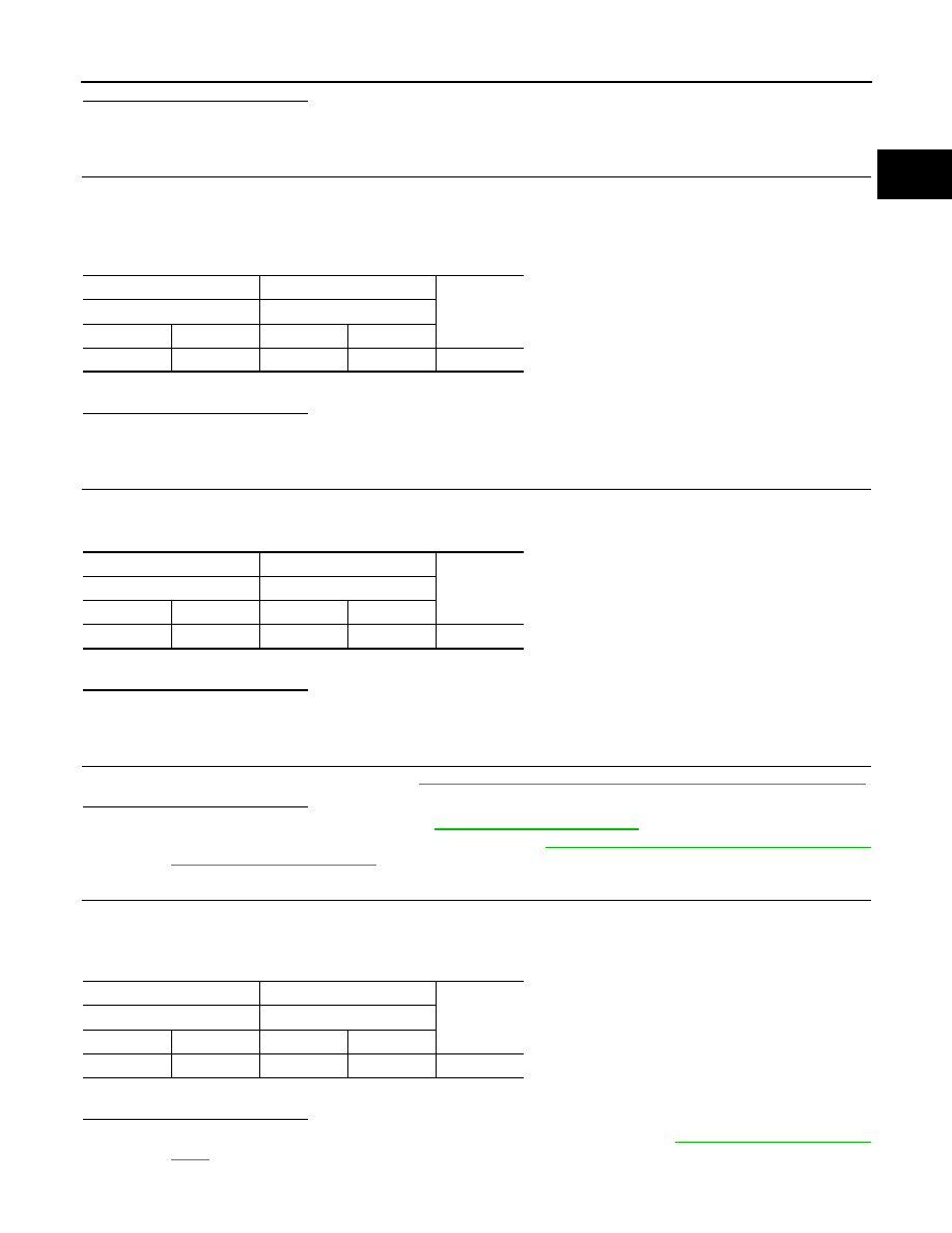
CHECK EGR VOLUME CONTROL VALVE POSITION SENSOR GROUND CIRCUIT
1. Turn ignition switch OFF.
2. Disconnect ECM harness connector.
3. Check harness continuity between EGR volume control valve harness connector and ECM harness con-
nector.
4. Also check harness for short to ground and short to power.
Is the inspection result normal?
YES
>> GO TO 3.
NO
>> Repair or replace error-detected parts.
3.
CHECK EGR VOLUME CONTROL VALVE POSITION SENSOR INPUT SIGNAL CIRCUIT
1. Check harness continuity between EGR volume control valve harness connector and ECM harness con-
nector.
2. Also check harness for short to ground and short to power.
Is the inspection result normal?
YES
>> GO TO 4.
NO
>> Repair or replace error-detected parts.
4.
CHECK EGR VOLUME CONTROL VALVE
Check the EGR volume control valve. Refer to
EC-961, "Component Inspection (EGR Volume Control Valve)"
.
Is the inspection result normal?
YES
>> Check intermittent incident. Refer to
GI-45, "Intermittent Incident"
.
NO
>> Replace EGR volume control valve. Refer to
EC-600, "ENGINE CONTROL SYSTEM :
.
5.
CHECK EGR VOLUME CONTROL VALVE POSITION SENSOR POWER SUPPLY CIRCUIT
1. Turn ignition switch OFF.
2. Disconnect ECM harness connector.
3. Check the continuity between EGR volume control valve harness connector and ECM harness connector.
4. Also check harness for short to ground and short to power.
Is the inspection result normal?
YES
>> Perform the trouble diagnosis for ECM power supply circuit. Refer to
.
NO
>> Repair or replace error-detected parts.
+
−
Continuity
EGR volume control valve
ECM
Connector
Terminal
Connector
Terminal
F74
5
F23
43
Existed
+
−
Continuity
EGR volume control valve
ECM
Connector
Terminal
Connector
Terminal
F74
4
F24
68
Existed
+
−
Continuity
EGR volume control valve
ECM
Connector
Terminal
Connector
Terminal
F74
3
F23
30
Existed