Nissan Juke F15. Manual - part 537


  Index      Nissan     Nissan Juke F15 (2015 year) - Service and Repair Manual


Search            


Content   ..  535  536  537  538   ..


Nissan Juke F15. Manual - part 537


P0404 EGR VOLUME CONTROL VALVE

EC-961

< DTC/CIRCUIT DIAGNOSIS >

[MR EXCEPT FOR NISMO RS MODELS]

C

D

E

F

G

H

I

J

K

L

M

A

EC

N

P

O

P0404 EGR VOLUME CONTROL VALVE

DTC Logic

INFOID:0000000012198455

DTC DETECTION LOGIC

NOTE:

If DTC P0404 is displayed with DTC P044A, or P044E, first perform trouble diagnosis for DTC P044A, or

P044E. Refer to 

EC-993, "DTC Logic"

.

DTC CONFIRMATION PROCEDURE

1.

PRECONDITIONING

If DTC Confirmation Procedure has been previously conducted, always perform the following procedure

before conducting the next test.

1. Turn ignition switch OFF and wait at least 10 seconds.

2. Turn ignition switch ON.

3. Turn ignition switch OFF and wait at least 10 seconds.

>> GO TO 2.

2.

PERFORM DTC CONFIRMATION PROCEDURE

1. Start the engine when the following conditions are met.

2. Drive the vehicle at 50 km/h (32 MPH) or more for at least 5 seconds.

3. Check 1st trip DTC.
Is 1st trip DTC detected?

YES

>> Proceed to 

EC-961, "Diagnosis Procedure"

.

NO

>> INSPECTION END

Diagnosis Procedure

INFOID:0000000012198456

1.

CHECK EGR VOLUME CONTROL VALVE

Check the EGR volume control valve. Refer to 

EC-961, "Component Inspection (EGR Volume Control Valve)"

.

Is the inspection result normal?

YES

>> Check intermittent incident. Refer to 

GI-45, "Intermittent Incident"

.

NO

>> Replace EGR volume control valve. Refer to 

EC-600, "ENGINE CONTROL SYSTEM :

Component Parts Location"

.

Component Inspection (EGR Volume Control Valve)

INFOID:0000000012198457

1.

CHECK EGR VOLUME CONTROL VALVE-1
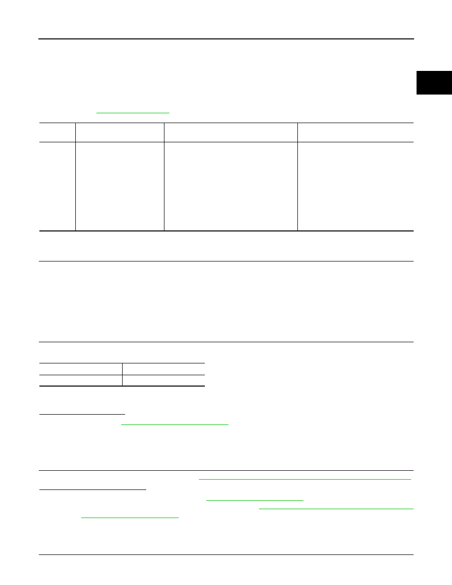
DTC No.

Trouble diagnosis name

(Trouble diagnosis content)

DTC detecting condition

Possible cause

P0404

EGR A CONTROL
(EGR A control circuit range/
performance)

• ECM detects that the current sent to the 

EGR volume control valve motor is equal to 
or more than the threshold value for 2 sec-
onds or more under the condition that the 
target angle of EGR volume control valve is 
constant.

• ECM detects that the difference between the 

target angle of EGR volume control valve 
and actual valve angle is equal to or more 
than the threshold value for 5 seconds or 
more.

• EGR volume control valve
• Foreigh objects interferes with EGR 

volume control valve

Intake air temperature

0

°C (32°F) or more

Engine coolant temperature 75

°C (167°F) or more

EC-962

< DTC/CIRCUIT DIAGNOSIS >

[MR EXCEPT FOR NISMO RS MODELS]

P0404 EGR VOLUME CONTROL VALVE

With CONSULT

1. Turn ignition switch ON and engine stopped.

2. On the CONSULT screen, select “ENGINE” >> “ACTIVE TEST” >> “EGR CONTROL VALVE”.

3. Operate “Up” or “Down”, set “EGR VALVE POSITION” to 0 deg, and check value “V1” of “EGR VALVE

POSITION SEN”.

Does “V1” become 1.2

±0.15 V?

YES

>> GO TO 2.

NO

>> Replace EGR volume control valve. Refer to 

EC-600, "ENGINE CONTROL SYSTEM :

Component Parts Location"

.

2.

CHECK EGR VOLUME CONTROL VALVE-2

With CONSULT

1. Operate “Up” or “Down”, set “EGR VALVE POSITION” to 70 deg, and check value “V2” of “EGR VALVE

POSITION SEN”.

Does “V2” become 4.0

±0.15 V?

YES

>> GO TO 3.

NO

>> Replace EGR volume control valve. Refer to 

EC-600, "ENGINE CONTROL SYSTEM :

Component Parts Location"

.

3.

CHECK EGR VOLUME CONTROL VALVE VISUALLY

1. Turn ignition switch OFF.

2. Check if any foreign objects interferes with EGR volume control valve.
Is the inspection result normal?

YES

>> INSPECTION END

NO

>> Repair or replace the error-detected parts.

P0407, P0408 EGR PRESSURE SENSOR

EC-963

< DTC/CIRCUIT DIAGNOSIS >

[MR EXCEPT FOR NISMO RS MODELS]

C

D

E

F

G

H

I

J

K

L

M

A

EC

N

P

O

P0407, P0408 EGR PRESSURE SENSOR

DTC Logic

INFOID:0000000012198458

DTC DETECTION LOGIC

DTC CONFIRMATION PROCEDURE

1.

PRECONDITIONING

If DTC Confirmation Procedure has been previously conducted, always perform the following procedure

before conducting the next test.

1. Turn ignition switch OFF and wait at least 10 seconds.

2. Turn ignition switch ON.

3. Turn ignition switch OFF and wait at least 10 seconds.

TEST CONDITION:

Before performing the following procedure, confirm that battery voltage is 11 V or more at ignition switch ON.

>> GO TO 2.

2.

PERFORM DTC CONFIRMATION PROCEDURE

1. Turn ignition switch ON and wait at least 5 seconds.

2. Check 1st trip DTC.
Is 1st trip DTC detected?

YES

>> Proceed to 

EC-963, "Diagnosis Procedure"

.

NO

>> INSPECTION END

Diagnosis Procedure

INFOID:0000000012198459

1.

CHECK EGR PRESSURE SENSOR POWER SUPPLY

1. Turn ignition switch OFF.

2. Disconnect EGR pressure sensor harness connector.

3. Turn ignition switch ON.

4. Check the voltage between EGR pressure sensor harness connector and ground.

Is the inspection result normal?

YES

>> GO TO 2.

NO

>> GO TO 5.

2.

CHECK EGR PRESSURE SENSOR GROUND CIRCUIT

1. Turn ignition switch OFF.

2. Disconnect ECM harness connector.

3. Check the continuity between EGR pressure sensor harness connector and ECM harness connector.

DTC No.

Trouble diagnosis name

(Trouble diagnosis content)

DTC detecting condition

Possible cause

P0407

EGR SENSOR B
(EGR sensor B circuit low)

ECM detects the following status continuously 
for 5 seconds or more:
A voltage signal transmitted from the EGR 
pressure sensor is 0.294 V or less.

• Harness or connectors

(EGR pressure sensor circuit is open 
or shorted.)

• EGR pressure sensor

P0408

EGR SENSOR B
(EGR sensor B circuit high)

ECM detects the following status continuously 
for 5 seconds or more:
A voltage signal transmitted from the EGR 
pressure sensor is 4.84 V or more.

+

Voltage

(Approx.)

EGR pressure sensor

Connector

Terminal

F46

1

Ground

5 V

EC-964

< DTC/CIRCUIT DIAGNOSIS >

[MR EXCEPT FOR NISMO RS MODELS]

P0407, P0408 EGR PRESSURE SENSOR

4. Also check harness for short to power.
Is the inspection result normal?

YES

>> GO TO 3.

NO

>> Repair or replace error-detected parts.

3.

CHECK EGR PRESSURE SENSOR INPUT SIGNAL CIRCUIT

1. Check the continuity between EGR pressure sensor harness connector and ECM harness connector.

2. Also check harness for short to ground and to power.
Is the inspection result normal?

YES

>> GO TO 4.

NO

>> Repair or replace error-detected parts.

4.

CHECK EGR PRESSURE SENSOR

Check the EGR pressure sensor. Refer to 

EC-1026, "Component Inspection"

.

Is the inspection result normal?

YES

>> Check intermittent incident. Refer to 

GI-45, "Intermittent Incident"

.

NO

>> Replace EGR pressure sensor.

5.

CHECK EGR PRESSURE SENSOR POWER SUPPLY CIRCUIT

1. Turn ignition switch OFF.

2. Disconnect ECM harness connector.

3. Check the continuity between EGR pressure sensor harness connector and ECM harness connector.

4. Also check harness for short to ground and short to power.
Is the inspection result normal?

YES

>> Perform the trouble diagnosis for power supply circuit.

NO

>> Repair or replace error-detected parts.

Component Inspection (EGR pressure sensor)

INFOID:0000000012198460

1.

CHECK EGR PRESSURE SENSOR

1. Turn ignition switch OFF.

2. Remove EGR pressure sensor hose (intake and exhaust).

3. Install pressure pump to EGR pressure sensor port (intake side).

4. Turn ignition switch ON and check output voltage between ECM connector terminals as follows.

+

Continuity

EGR pressure sensor

ECM

Connector

Terminal

Connector

Terminal

F46

3

F23

43

Existed

+

Continuity

EGR pressure sensor

ECM

Connector

Terminal

Connector

Terminal

F46

2

F23

24

Existed

+

Continuity

EGR pressure sensor

ECM

Connector

Terminal

Connector

Terminal

F46

1

F23

30

Existed


Content   ..  535  536  537  538   ..