Nissan Juke F15. Manual - part 309
SYSTEM
EC-49
< SYSTEM DESCRIPTION >
[MR FOR NISMO RS MODELS]
C
D
E
F
G
H
I
J
K
L
M
A
EC
N
P
O
SYSTEM
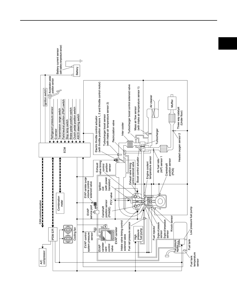
ENGINE CONTROL SYSTEM
ENGINE CONTROL SYSTEM : System Diagram
INFOID:0000000012197664
ENGINE CONTROL SYSTEM : System Description
INFOID:0000000012197665
ECM controls the engine by various functions.
JPBIA5480GB