Nissan Juke F15. Manual - part 308


  Index      Nissan     Nissan Juke F15 (2015 year) - Service and Repair Manual


Search            


Content   ..  306  307  308  309   ..


Nissan Juke F15. Manual - part 308


COMPONENT PARTS

EC-45

< SYSTEM DESCRIPTION >

[MR FOR NISMO RS MODELS]

C

D

E

F

G

H

I

J

K

L

M

A

EC

N

P

O

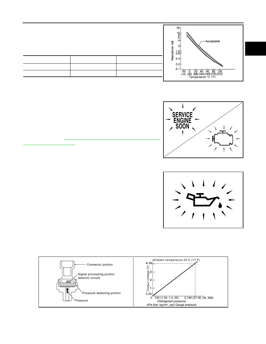
Battery temperature sensor is integrated in battery current sensor.

The sensor measures temperature around the battery.

The electrical resistance of the thermistor decreases as temperature

increases.

<Reference data>

*: These data are reference values and are measured between battery temperature
sensor signal terminal and sensor ground.

Malfunction Indicator lamp (MIL)

INFOID:0000000012197655

The Malfunction Indicator lamp (MIL) is located on the combination

meter.

The MIL will illuminate when the ignition switch is turned ON without

the engine running. This is a bulb check.

When the engine is started, the MIL should turn OFF. If the MIL

remains illuminated, the on board diagnostic system has detected an

engine system malfunction.

For details, refer to 

EC-81, "DIAGNOSIS DESCRIPTION : Malfunc-

tion Indicator Lamp (MIL)"

.

Oil Pressure Warning Lamp

INFOID:0000000012197656

Oil pressure warning lamp is located on the combination meter. 

It indicates the low pressure of the engine oil and the malfunction of

the engine oil pressure system.

Combination meter turns the oil pressure warning lamp ON/OFF

according to the oil pressure warning lamp signal received from

ECM via CAN communication.

Refrigerant Pressure Sensor

INFOID:0000000012197657

The refrigerant pressure sensor is installed at the condenser of the air conditioner system. The sensor uses an

electrostatic volume pressure transducer to convert refrigerant pressure to voltage. The voltage signal is sent

to ECM, and ECM controls cooling fan system.

Stop Lamp Switch & Brake Pedal Position Switch

INFOID:0000000012197658

Stop lamp switch and brake pedal position switch are installed to brake pedal bracket.

ECM detects the state of the brake pedal by those two types of input (ON/OFF signal).

Temperature [

°C (°F)]

Voltage

*

 (V)

Resistance (k

Ω)

25 (77)

3.333

1.9 - 2.1

90 (194)

0.969

0.222 - 0.258

SEF012P

JSBIA1315ZZ

PBIA8559J

PBIB2657E

EC-46

< SYSTEM DESCRIPTION >

[MR FOR NISMO RS MODELS]

COMPONENT PARTS

Clutch Pedal Position Switch

INFOID:0000000012197659

When the clutch pedal is depressed, the clutch pedal position switch turns OFF and the clutch pedal position

switch signal is sent to the ECM. The ECM judges the clutch pedal conditions via the signal (ON or OFF).

ASCD Steering Switch

INFOID:0000000012197660

ASCD steering switch has variant values of electrical resistance for each button. ECM reads voltage variation

of switch, and determines which button is operated.

Information Display

INFOID:0000000012197661

The operation mode of the ASCD is indicated on the information display in the combination meter.

ECM transmits the status signal to the combination meter via CAN communication according to ASCD opera-

tion.

Brake pedal

Brake pedal position switch

Stop lamp switch

Released

ON

OFF

Depressed

OFF

ON

STRUCTURE AND OPERATION

EC-47

< SYSTEM DESCRIPTION >

[MR FOR NISMO RS MODELS]

C

D

E

F

G

H

I

J

K

L

M

A

EC

N

P

O

STRUCTURE AND OPERATION

Positive Crankcase Ventilation

INFOID:0000000012197662

This system returns blow-by gas to the intake manifold.

The positive crankcase ventilation (PCV) valve is provided to conduct crankcase blow-by gas to the intake

manifold.

During partial throttle operation of the engine, the intake manifold sucks the blow-by gas through the PCV

valve.

Normally, the capacity of the valve is sufficient to handle any blow-by and a small amount of ventilating air.

The ventilating air is then drawn from the air inlet tubes into the crankcase. In this process the air passes

through the hose connecting air inlet tubes to rocker cover.

Under full-throttle condition, the manifold vacuum is insufficient to draw the blow-by flow through the valve.

The flow goes through the hose connection in the reverse direction.

On vehicles with an excessively high blow-by, the valve does not

meet the requirement. This is because some of the flow will go

through the hose connection to the air inlet tubes under all condi-

tions.

PBIB0492E

PBIB1588E

EC-48

< SYSTEM DESCRIPTION >

[MR FOR NISMO RS MODELS]

STRUCTURE AND OPERATION

On Board Refueling Vapor Recovery (ORVR)

INFOID:0000000012197663

From the beginning of refueling, the air and vapor inside the fuel tank go through refueling EVAP vapor cut

valve and EVAP/ORVR line to the EVAP canister. The vapor is absorbed by the EVAP canister and the air is

released to the atmosphere.

When the refueling has reached the full level of the fuel tank, the refueling EVAP vapor cut valve is closed and

refueling is stopped because of auto shut-off. The vapor which was absorbed by the EVAP canister is purged

during driving.

WARNING:

When conducting inspections below, be sure to observe the following:

• Put a “CAUTION: FLAMMABLE” sign in workshop.

• Do not smoke while servicing fuel system. Keep open flames and sparks away from work area.

• Be sure to furnish the workshop with a CO

2

 fire extinguisher.

CAUTION:

• Before removing fuel line parts, carry out the following procedures:

- Put drained fuel in an explosion-proof container and put lid on securely.

- Release fuel pressure from fuel line. Refer to 

EC-586, "Inspection"

.

- Disconnect battery ground cable.

• Always replace O-ring when the fuel gauge retainer is removed.

• Do not kink or twist hose and tube when they are installed.

• Do not tighten hose and clamps excessively to avoid damaging hoses.

• After installation, run engine and check for fuel leaks at connection.

• Do not attempt to top off the fuel tank after the fuel pump nozzle shuts off automatically.

Continued refueling may cause fuel overflow, resulting in fuel spray and possibly a fire.

JMBIA1930GB


Content   ..  306  307  308  309   ..