Nissan Juke F15. Manual - part 273


  Index      Nissan     Nissan Juke F15 (2015 year) - Service and Repair Manual


Search            


Content   ..  271  272  273  274   ..


Nissan Juke F15. Manual - part 273


RING GEAR SHAFT

DLN-97

< UNIT DISASSEMBLY AND ASSEMBLY >

[TRANSFER: TY21B]

C

E

F

G

H

I

J

K

L

M

A

B

DLN

N

O

P

Disassembly

INFOID:0000000012199466

1. Remove transfer cover. Refer to 

DLN-117, "Disassembly"

.

2. Remove transfer case oil seal (right and left).
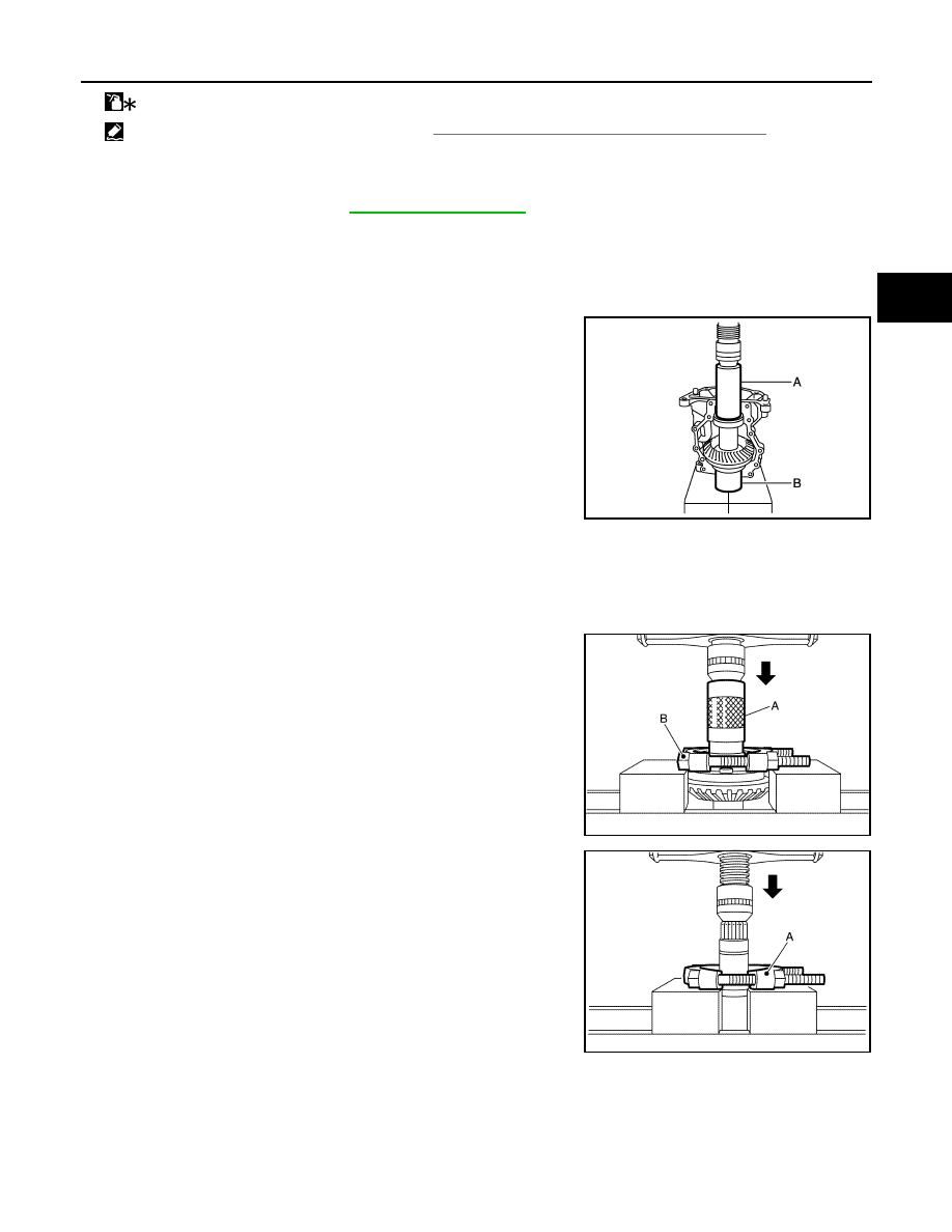
3. Remove ring gear shaft assembly from transfer case. If ring gear shaft cannot be removed, remove as fol-

lows.

CAUTION:

Never damage transfer case.

• Set the drifts (A and B) to right and left spacers individually.

Compress ring gear shaft assembly with ring gear bearing to

remove ring gear shaft assembly from transfer case.

CAUTION:

• The drift shall be placed on the center of the spacers.

• The pressure shall be as low as to remove ring gear

shaft assembly from transfer case. The maximum pres-

sure shall be 10 kN (1 ton, 1.0 Imp ton).

• If the adjusting shims and spacers are installed by tap-

ping, the transfer case may be damaged. Avoid tapping.

4. Remove spacer (right and left) from ring gear shaft assembly.
5. Remove ring gear bearing adjusting shim (right and left) from ring gear shaft assembly.
6. Remove outer races of ring gear bearing (right and left) from ring gear shaft assembly.
7. Remove inner race of ring gear bearing (right) from ring gear

shaft with the drift (A) and the replacer (B).

8. Remove inner race of ring gear bearing (left) from ring gear shaft

with the replacer (A) (Commercial service tool).

9. Remove the ring gear mounting bolts.

: Apply anti-corrosive oil.

: Apply Genuine Silicone RTV or equivalent. Refer to 

GI-22, "Recommended Chemical Products and Sealants"

.

A

: Drift (Commercial service tool)

B

: Drift (Commercial service tool)

A

: Drift [SST: ST33200000 (J-26082)]

B

: Replacer (Commercial service tool)

JSDIA1106ZZ

JSDIA2165ZZ

JSDIA2166ZZ

DLN-98

< UNIT DISASSEMBLY AND ASSEMBLY >

[TRANSFER: TY21B]

RING GEAR SHAFT

10. Lightly tap ring gear with a plastic hammer to remove ring gear

from ring gear shaft.

11. Remove drive shaft oil seal from the ring gear shaft with the

puller (A) [SST: KV381054S0 (J-34286)].

12. Perform inspection after disassembly. Refer to 

DLN-109,

"Inspection"

.

Assembly

INFOID:0000000012199467

1. Select ring gear bearing adjusting shim (right and left). Refer to 

DLN-99, "Adjustment"

.

2. Using the drift (A) [SST: ST33230000 (J-25805-01)], install drive

shaft oil seal (1) within the dimension (L) shown as follows.

CAUTION:

• Never reuse the oil seal.

• When installing, never incline oil seal.

• Apply multi-purpose grease to oil seal lip, and gear oil

onto the circumference.

3. Install the ring gear to ring gear shaft.

4. Install the inner race of ring gear bearing (left) to ring gear shaft

with the drift (A) (Commercial service tool).

CAUTION:

• Never reuse the ring gear bearing.

• Apply gear oil to ring gear bearing.

SDIA1807J

JPDIE0032ZZ

L

: 0 – 0.6 mm (0 – 0.024 in)

JSDIA2492ZZ

JSDIA1055ZZ

RING GEAR SHAFT

DLN-99

< UNIT DISASSEMBLY AND ASSEMBLY >

[TRANSFER: TY21B]

C

E

F

G

H

I

J

K

L

M

A

B

DLN

N

O

P

5. Install the inner race of ring gear bearing (right) to ring gear shaft

with the drift (A) (Commercial service tool).

CAUTION:

• Never reuse the ring gear bearing.

• Apply gear oil to ring gear bearing.

6. Install outer races of ring gear bearing (right and left) to ring gear

shaft assembly.

CAUTION:

• Never reuse the ring gear bearing.

• Apply gear oil to ring gear bearing.

7. Install selected ring gear bearing adjusting shim (right and left)

to ring gear shaft assembly.

8. Install spacer (right and left) to ring gear shaft assembly.
9. Set the drifts (A and B) to right and left spacers individually.

Compress ring gear shaft assembly with ring gear bearing to

install ring gear shaft assembly to transfer case.

CAUTION:

• The drift shall be placed on the center of the spacers.

• The pressure shall be as low as to install ring gear shaft

assembly into transfer case. The maximum pressure shall

be 10 kN (1 ton, 1.0 Imp ton).

• If the adjusting shims and spacers are installed by tap-

ping, the transfer case may be damaged. Avoid tapping.

10. Install transfer cover to check and adjust each part. Refer to 

DLN-117, "Assembly"

.

CAUTION:

Never apply liquid gasket.

11. Check backlash, tooth contact, and total preload. Refer to 

DLN-99, "Adjustment"

.

CAUTION:

Measure the total preload without the transfer case oil seal.

12. Reinstall transfer cover for applying liquid gasket. Refer to 

DLN-117, "Assembly"

.

13. Install the transfer case oil seal (left and right). Refer to 

DLN-117, "Assembly"

.

Adjustment

INFOID:0000000012199468

Adjusting shim selection

A

: Drift (Commercial service tool)

B

: Drift (Commercial service tool)

JSDIA1056ZZ

JSDIA1106ZZ

DLN-100

< UNIT DISASSEMBLY AND ASSEMBLY >

[TRANSFER: TY21B]

RING GEAR SHAFT

Measurement point

Ring gear bearing adjusting shim (left)

1. Measure the dimensions of each measuring point with the following procedure:

Dimension “A” measurement

• Measure dimension (A) of transfer case with a pair of vernier

calipers. Refer to “Measuring point”.

CAUTION:

Never damage transfer case.

Dimension “X” measurement

JSDIA2493ZZ

JSDIA2170ZZ


Content   ..  271  272  273  274   ..