Nissan Juke F15. Manual - part 222
DLK-68
< DTC/CIRCUIT DIAGNOSIS >
[WITH INTELLIGENT KEY SYSTEM]
DOOR LOCK ACTUATOR
DOOR LOCK ACTUATOR
DRIVER SIDE
DRIVER SIDE : Component Function Check
INFOID:0000000012196627
1.
CHECK FUNCTION
1. Select “DOOR LOCK” of “BCM” using CONSULT.
2. Select “DOOR LOCK” in “ACTIVE TEST” mode.
3. Check that the function operates normally according to the following conditions.
Is the inspection result normal?
YES
>> Door lock actuator is OK.
NO
>> Refer to
DLK-68, "DRIVER SIDE : Diagnosis Procedure"
DRIVER SIDE : Diagnosis Procedure
INFOID:0000000012196628
1.
CHECK DOOR LOCK ACTUATOR INPUT SIGNAL
1. Turn ignition switch OFF.
2. Disconnect front door lock assembly (driver side) connector.
3. Check voltage between front door lock assembly (driver side) harness connector and ground.
Is the inspection result normal?
YES
>> Replace front door lock assembly (driver side).
NO
>> GO TO 2.
2.
CHECK DOOR LOCK ACTUATOR CIRCUIT
1. Disconnect BCM connector and all door lock assembly connector.
2. Check continuity between BCM harness connector and front door lock assembly (driver side) harness
connector.
3. Check continuity between BCM harness connector and ground.
Is the inspection result normal?
YES
>> GO TO 3.
NO
>> Repair or replace harness.
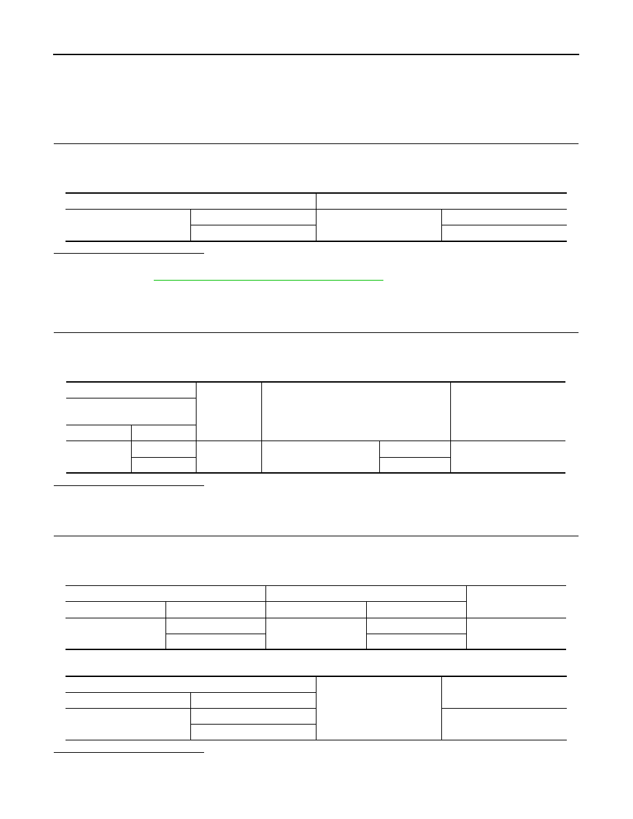
Monitor item
Status
DOOR LOCK
ALL LOCK
Door lock actuators
LOCK
ALL UNLK
UNLOCK
(+)
(–)
Condition
Voltage
(Approx.)
Front door lock assembly
(driver side)
Connector
Terminal
D38
2
Ground
Door lock and unlock switch
Unlock
12 V
1
Lock
BCM
Front door lock assembly (driver side)
Continuity
Connector
Terminal
Connector
Terminal
M69
65
D38
1
Existed
66
2
BCM
Ground
Continuity
Connector
Terminal
M69
65
Not existed
66