Content .. 1374 1375 1376 1377 ..
Nissan Juke F15. Manual - part 1376
SERVICE DATA AND SPECIFICATIONS (SDS)
WT-47
< SERVICE DATA AND SPECIFICATIONS (SDS)
C
D
F
G
H
I
J
K
L
M
A
B
WT
N
O
P
SERVICE DATA AND SPECIFICATIONS (SDS)
SERVICE DATA AND SPECIFICATIONS (SDS)
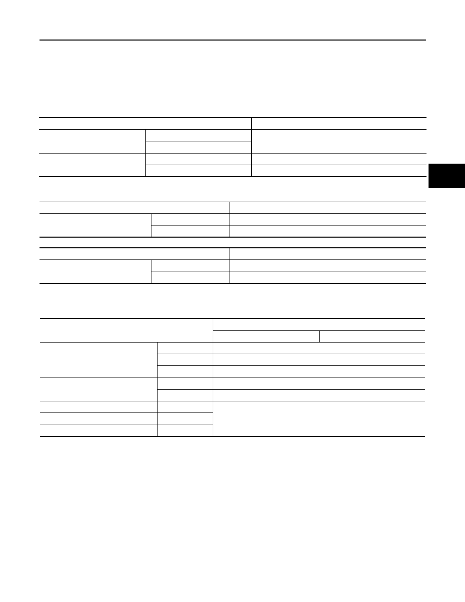
Road Wheel
INFOID:0000000012201877
CONVENTIONAL
EMERGENCY
Except NISMO RS
NISMO RS
Tire Air Pressure
INFOID:0000000012201878
Unit: kPa (kgf/cm
2
, psi)
Item
Limit
Runout
Axial runout
Less than 0.3 mm (0.012 in)
Radial runout
Allowable unbalance
Dynamic (At flange)
Less than 5 g (0.17 oz) (one side)
Static (At flange)
Less than 10 g (0.35 oz)
Item
Limit
Runout
Axial runout (Average)
Less than 1.2 mm (0.047 in)
Radial runout (Average)
Less than 1.3 mm (0.051 in)
Item
Limit
Runout
Axial runout (Average)
Less than 1.5 mm (0.059 in)
Radial runout (Average)
Less than 1.5 mm (0.059 in)
Item
Standard
Front
Rear
P215/55R17 93V
M/T
230 (2.3, 33)
CVT(2WD)
250 (2.5, 36)
CVT(AWD)
240 (2.4, 35)
225/45R18 95Y
2WD
230 (2.3, 33)
AWD
240 (2.4, 35)
T135/80D16 101M
2WD
420 (4.2, 60)
T135/90D16 102M
AWD
T135/70D17 92M
NISMO RS