Nissan Juke F15. Manual - part 1375


  Index      Nissan     Nissan Juke F15 (2015 year) - Service and Repair Manual


Search            


Content   ..  1373  1374  1375  1376   ..


Nissan Juke F15. Manual - part 1375


TIRE PRESSURE SENSOR

WT-43

< REMOVAL AND INSTALLATION >

C

D

F

G

H

I

J

K

L

M

A

B

WT

N

O

P

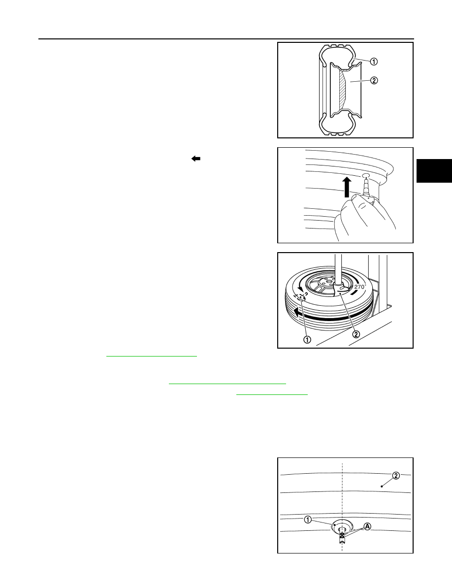
2. Install the tire inside beads (1) onto the road wheel (2) in the

position shown in the figure.

3. Install grommet seal to the tire pressure sensor.

CAUTION:

• Never reuse grommet seal.

• Insert grommet seal all the way to the base.

4. Hold tire pressure sensor as shown in the figure, and press the

sensor in the direction shown by arrow (

) to bring it into abso-

lute contact with valve hole. After this, tighten valve nut to the

specified torque.

CAUTION:

• Never reuse valve core and valve cap.

• Check that grommet seal is free of foreign matter.

• Check that grommet seal contacts horizontally with road

wheel.

• Manually tighten valve nut all the way to the wheel. (Never

use a power tool to avoid impact.)

5. Set the tire onto the turntable so that the tire changer arm (2) is

at a position approximately 270

° from the tire pressure sensor

(1).

CAUTION:

Be sure that the arm does not contact the tire pressure sen-

sor.

6. Install the tire outer side beads onto the road wheel.

CAUTION:

When installing, check that the tire does not turn together

with the road wheel.

7. Check the tire pressure for all wheels and adjust to the specified

value. Refer to 

WT-47, "Tire Air Pressure"

.

NOTE:

Before adding air, align the tire with the position of the matching mark applied at the time of removal.

8. Install tire to the vehicle. Refer to 

WT-39, "Removal and Installation"

.

9. Perform tire pressure sensor ID registration. Refer to 

WT-20, "Description"

.

Snap-in Type

1. Install valve, follow the procedure below.
a. Set the valve to road wheel.

CAUTION:

• Never reuse valve

• Check the valve (1) direction, part (A) of valve must be at 12 o’clock

 to the rim of road wheel (2).

JPEIC0105ZZ

JSEIA0466GB

JPEIC0014GB

JSEIA1402ZZ

WT-44

< REMOVAL AND INSTALLATION >

TIRE PRESSURE SENSOR

b. Install the valve (1) to road wheel (2), using a valve inserter (A).

CAUTION:

• Be sure not to damage the road wheel.

• Insert valve all the way to the road wheel.

• Check that valve contacts horizontally with road wheel.

• Check the valve (1) direction, part (A) of valve must be at

12 o’clock to the rim of road wheel (2).

• If the position is not correct, rotate the valve to the correct

position, using a valve inserter. 

2. Install the tire pressure sensor, follow the procedure below.
a. Insert the tire pressure sensor (1) to the roll pin (A) of valve (2).

b. Install the stopper (1) until locked in the direction (A) by hands.

CAUTION:

• Never reuse stopper.

• Be sure not to damage the tire pressure sensor.

JSEIA1394ZZ

JSEIA1402ZZ

JSEIA1403ZZ

JSEIA1404ZZ

TIRE PRESSURE SENSOR

WT-45

< REMOVAL AND INSTALLATION >

C

D

F

G

H

I

J

K

L

M

A

B

WT

N

O

P

• Be careful with the orientation of stopper (1).

• Pull on the tire pressure sensor to check that the tire pres-

sure sensor is correctly locked on the valve.

• Tire pressure sensor must be oriented tangentially to rim

of road wheel drop-well.

3. Apply bead cream or an equivalent to the tire beads.
4. Install the tire inside beads (1) onto the road wheel (2) in the

position shown in the figure.

5. Set the tire onto the turntable so that the tire changer arm (2) is

at a position approximately 270

° from the tire pressure sensor

(1).

CAUTION:

Be sure that the arm does not contact the tire pressure sen-

sor.

6. Install the tire outer side beads onto the road wheel.

CAUTION:

When installing, check that the tire does not turn together

with the road wheel.

7. Check the tire pressure for all wheels and adjust to the specified

value. Refer to 

WT-47, "Tire Air Pressure"

.

NOTE:

Before adding air, align the tire with the position of the matching mark applied at the time of removal.

8. Install tire to the vehicle. Refer to 

WT-39, "Removal and Installation"

.

9. Perform tire pressure sensor ID registration. Refer to 

WT-20, "Description"

.

(A)

: Protrusions of stopper

(B)

: Valve side

JSEIA1405ZZ

JPEIC0105ZZ

JPEIC0014GB

WT-46

< REMOVAL AND INSTALLATION >

TIRE PRESSURE RECEIVER

TIRE PRESSURE RECEIVER

Removal and Installation

INFOID:0000000012201876

REMOVAL

1. Remove the remote keyless entry receiver. (The tire pressure receiver is incorporated into keyless entry

receiver.) Refer to 

DLK-174, "Removal and Installation"

.

INSTALLATION

Install in the reverse order of removal.


Content   ..  1373  1374  1375  1376   ..