Nissan Juke F15. Manual - part 131


  Index      Nissan     Nissan Juke F15 (2015 year) - Service and Repair Manual


Search            


Content   ..  129  130  131  132   ..


Nissan Juke F15. Manual - part 131


C1155 BRAKE FLUID LEVEL SWITCH

BRC-115

< DTC/CIRCUIT DIAGNOSIS >

[WITH VDC]

C

D

E

G

H

I

J

K

L

M

A

B

BRC

N

O

P

6. Check the combination meter harness connector for disconnection or looseness.

7. Check the combination meter pin terminals for damage or loose connection with harness connector.
Is the inspection result normal?

YES

>> GO TO 9.

NO

>> Repair / replace harness, connector, or terminal, and GO TO 8.

8.

PERFORM SELF-DIAGNOSIS (4)

With CONSULT

1. Connect brake fluid level switch harness connector.

2. Connect combinetion meter harness connector.

3. Erase self-diagnosis result for “ABS”.

4. Turn the ignition switch OFF 

→ ON → OFF.

NOTE:

Wait at least 10 seconds after turning ignition switch OFF or ON.

5. Start the engine.

NOTE:

Wait at least 10 seconds after start the engine.

6. Perform self-diagnosis for “ABS”.
Is DTC “C1155” detected?

YES

>> GO TO 9.

NO

>> INSPECTION END

9.

CHECK BRAKE FLUID LEVEL SWITCH CIRCUIT

1. Turn the ignition switch OFF.

2. Disconnect brake fluid level switch harness connector.

3. Disconnect combination meter harness connector.

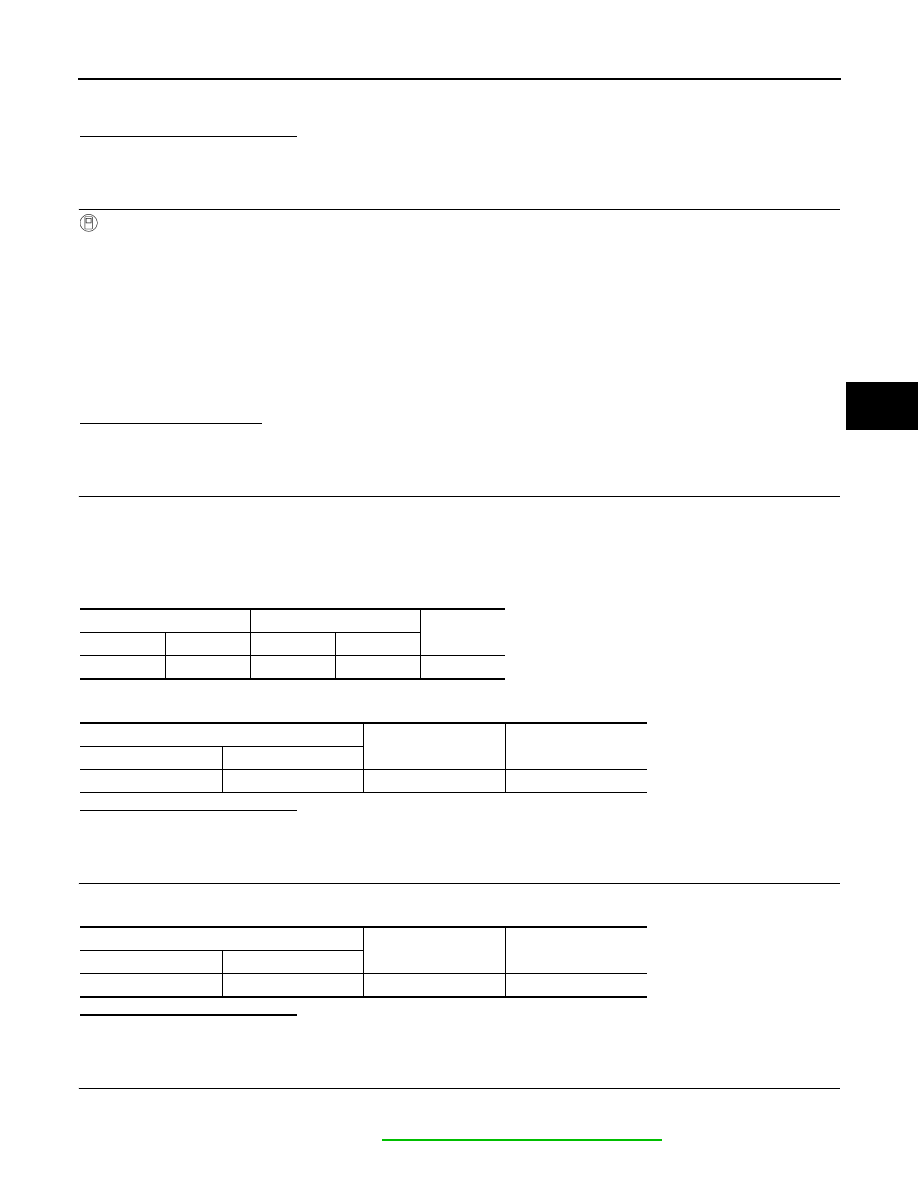
4. Check the continuity between brake fluid level switch harness connector and combination meter harness

connector.

5. Check the continuity between brake fluid level switch harness connector and ground.

Is the inspection result normal?

YES

>> GO TO 10.

NO

>> Repair / replace harness or connector, and GO TO 10.

10.

CHECK BRAKE FLUID LEVEL SWITCH GROUND CIRCUIT

Check the continuity between brake fluid level switch harness connector and ground.

Is the inspection result normal?

YES

>> GO TO 11.

NO

>> Repair / replace harness or connector, and GO TO 11.

11.

CHECK COMBINATION METER

1. Connect brake fluid level switch harness connector.

2. Connect combinetion meter harness connector.

3. Check the combination meter. Refer to 

MWI-21, "On Board Diagnosis Function"

.

Brake fluid level switch

Combination meter

Continuity

Connector

Terminal

Connector

Terminal

E37

1

M34

11

Existed

Brake fluid level switch

Continuity

Connector

Terminal

E37

1

Ground

Not existed

Brake fluid level switch

Continuity

Connector

Terminal

E37

2

Ground

Existed

BRC-116

< DTC/CIRCUIT DIAGNOSIS >

[WITH VDC]

C1155 BRAKE FLUID LEVEL SWITCH

Is the inspection result normal?

YES

>> Replace the ABS actuator and electric unit (control unit). Refer to 

BRC-153, "Removal and Instal-

lation"

.

NO

>> Repair or replace combination meter. Refer to 

MWI-64, "Removal and Installation"

.

Component Inspection

INFOID:0000000012199711

1.

CHECK BRAKE FLUID LEVEL SWITCH

1. Turn the ignition switch OFF.

2. Disconnect brake fluid level switch harness connector.

3. Check the continuity between brake fluid level switch connector terminals.

Is the inspection result normal?

YES

>> INSPECTION END

NO

>> Replace the reservoir tank. Refer to 

BR-40, "Disassembly and Assembly"

.

Brake fluid level switch

Condition

Continuity

Terminal

1 – 2

When brake fluid level in reservoir tank is within the specified level.

Not existed

When brake fluid level in reservoir tank is less than the specified 
level.

Existed

C1164, C1165 CV SYSTEM

BRC-117

< DTC/CIRCUIT DIAGNOSIS >

[WITH VDC]

C

D

E

G

H

I

J

K

L

M

A

B

BRC

N

O

P

C1164, C1165 CV SYSTEM

DTC Logic

INFOID:0000000012199712

DTC DETECTION LOGIC

POSSIBLE CAUSE

NOTE:

Confirm if DTC is PAST or CRNT. If DTC is CRNT, proceed with Diagnosis Procedure. If DTC is PAST, clear

DTC. Do not replace the ABS actuator and electric unit (control unit) for a PAST DTC.

DTC CONFIRMATION PROCEDURE

1.

PRECONDITIONING

If “DTC CONFIRMATION PROCEDURE” has been previously conducted, always turn the ignition switch OFF

and wait at least 10 seconds before conducting the next test.

>> GO TO 2.

2.

CHECK DTC DETECTION

With CONSULT

1. Turn the ignition switch OFF.

NOTE:

Wait at least 10 seconds after turning ignition switch OFF.

2. Start the engine.

NOTE:

Wait at least 10 seconds after start the engine.

3. Perform self-diagnosis for “ABS”.
Is DTC “C1164” or “C1165” detected?

YES-1 >> “C1164” or “C1165” is displayed by “CRNT”: Proceed to 

BRC-117, "Diagnosis Procedure"

.

YES-2 >> “C1164” and “C1165” are displayed by “PAST”: INSPECTION END (Erase the memory of self-

diagnosis results.)

NO-1 >> To check malfunction symptom before repair: Refer to 

GI-45, "Intermittent Incident"

.

NO-2 >> Confirmation after repair: INSPECTION END

Diagnosis Procedure

INFOID:0000000012199713

1.

CHECK CONNECTOR

1. Turn the ignition switch OFF.

2. Check the ABS actuator and electric unit (control unit) harness connector for disconnection or looseness.
Is the inspection result normal?

YES

>> GO TO 3.

DTC

Display Item

(Trouble diagnosis content)

Malfunction detected condition

C1164

CV 1
(Cut valve 1)

When a malfunction is detected in cut valve 1.

C1165

CV 2
(Cut valve 2)

When a malfunction is detected in cut valve 2.

PAST DTC

CRNT DTC

• Harness or connector
• ABS actuator and electric unit (control unit) power supply sys-

tem

• Fuse
• Fusible link
• Battery

• Harness or connector
• ABS actuator and electric unit (control unit)
• ABS actuator and electric unit (control unit) power supply sys-

tem

• Fuse
• Fusible link
• Battery

BRC-118

< DTC/CIRCUIT DIAGNOSIS >

[WITH VDC]

C1164, C1165 CV SYSTEM

NO

>> Repair / replace harness or connector, securely lock the connector, and GO TO 2.

2.

PERFORM SELF-DIAGNOSIS

With CONSULT

Perform self-diagnosis for “ABS” again.
Is DTC “C1164” or “C1165” detected?

YES

>> GO TO 3.

NO

>> INSPECTION END

3.

CHECK ABS ACTUATOR AND ELECTRIC UNIT (CONTROL UNIT) POWER SUPPLY AND GROUND CIR-

CUIT
Check the ABS actuator and electric unit (control unit) power supply and ground circuit. Refer to 

BRC-129,

"Diagnosis Procedure"

.

Is the inspection result normal?

YES

>> GO TO 4.

NO

>> Repair / replace harness, connector, fuse, or fusible link.

4.

CHECK TERMINAL

Check the ABS actuator and electric unit (control unit) pin terminals for damage or loose connection with har-

ness.
Is the inspection result normal?

YES

>> Replace the ABS actuator and electric unit (control unit). Refer to 

BRC-153, "Removal and Instal-

lation"

.

NO

>> Repair / replace harness, connector, or terminal.


Content   ..  129  130  131  132   ..